|
Last Updated
23 June, 2005
|
|
|
Back to Start
Page
 1
2 3
4 5
6
7
8
9
10
1
2 3
4 5
6
7
8
9
10
 |
|
|
UNDER CONSTRUCTION
Installing the 3SGTE
|
|
| |
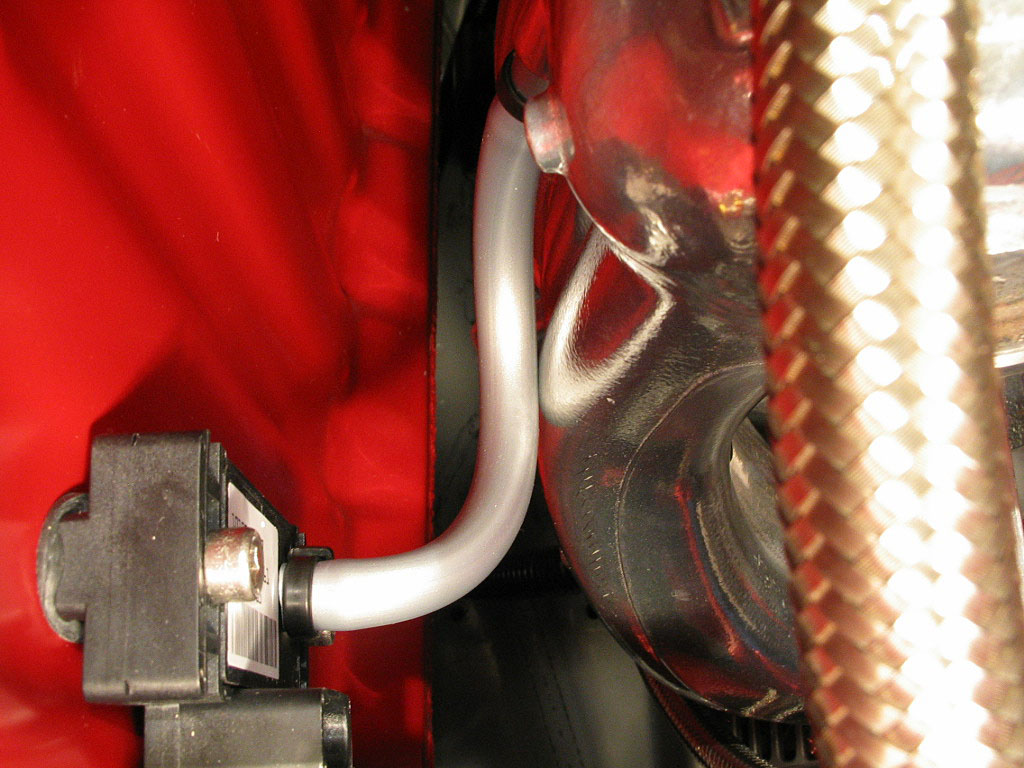
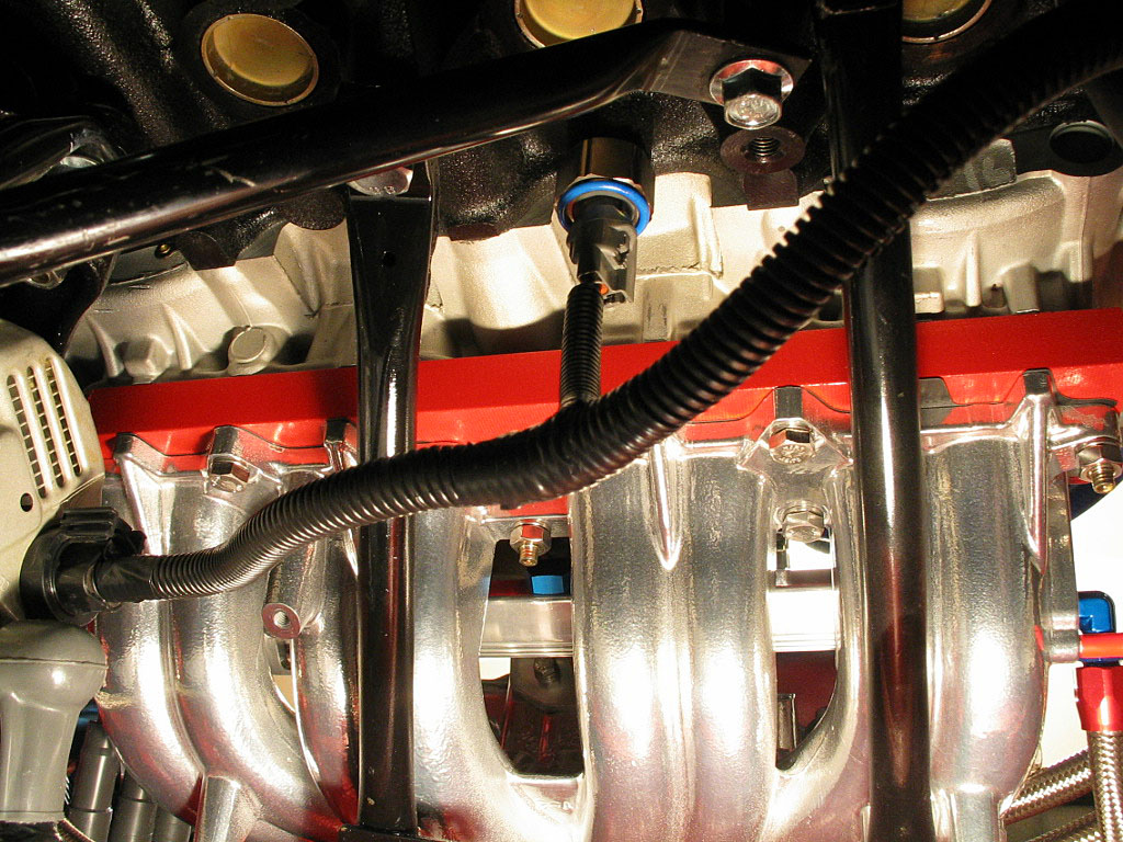
At this point, I could start running some of
the vacuum hose.
First, I needed a short run from the intake manifold to the MAP sensor:

I was using polypropylene cable ties as hose clamps. These ties are
rated to
215ş F.
|
|
| |
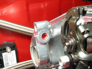
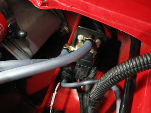
It was getting pretty crowded in the right
corner of the engine bay, so I plugged the hole for the stock brake
booster nipple...
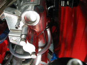
...attached a length of silicone hose to the brake booster pipe...

...and ran it back to an unused hose nipple on the back of the intake manifold:
|
|
| |
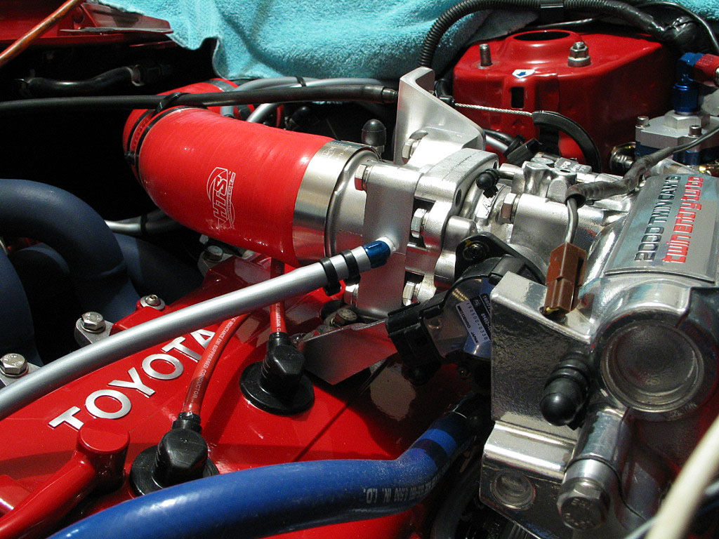
I'd
previously
installed a couple of Ľ" hose barbs into the throttle body intake, one
for the wastegate and one for the BOV. From the right-hand barb, I ran
a length of silicone hose to the COM port of the AVCR solenoid:
I teed off this line to the side port of the Tial wastegate. I also ran a
hose from the top port of the wastegate to the NO port of the solenoid:
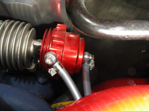
I used stainless hose clamps on the wastegate, due to the higher
temperatures.
|
|
| |
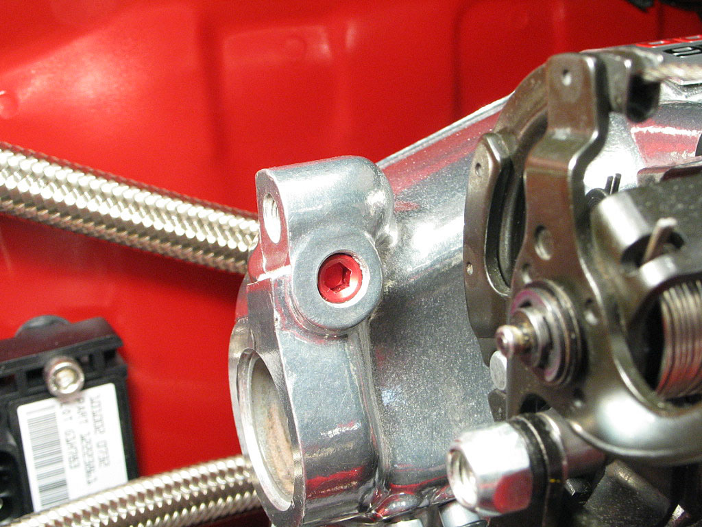
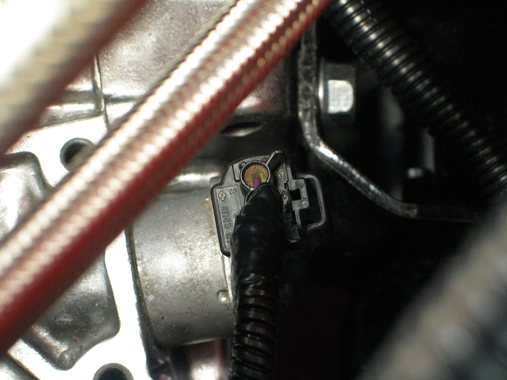
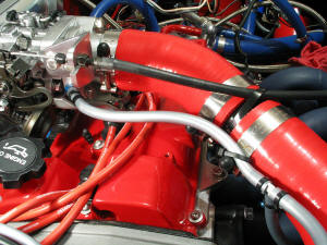
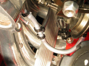
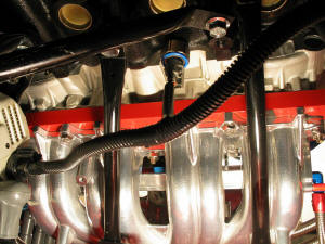
I ran a smaller vacuum hose from the intake
manifold to the throttle stop diaphragm. I teed off this to run a hose to
the port on the adjustable fuel pressure regulator (APR):
|
|
| |
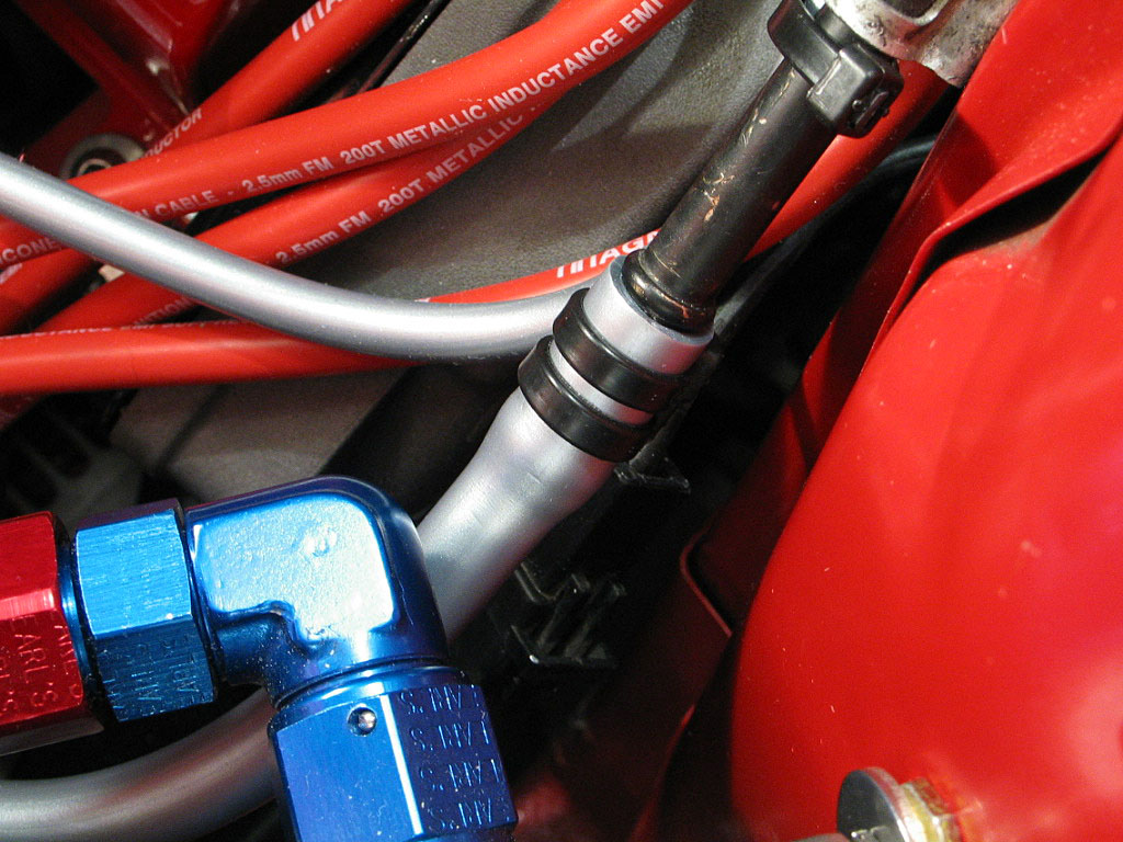
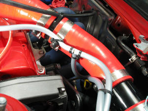
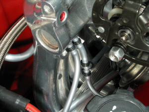
I ran a length of hose from the intake
manifold to the AVCR pressure sensor. Later, I'll tee into this line for
the boost gauge hose:
|
|
| |
Finally, I ran a hose from the hose barb on
the left side of the throttle body to the area where I mounted the BOV:

I'll cut it to length once I've finalized its path.
|
|
| |
Before I reinstalled the rear axles and
suspension, I wanted to wire up the alternator and knock sensor, as they
were very accessible now:
|
|
| |
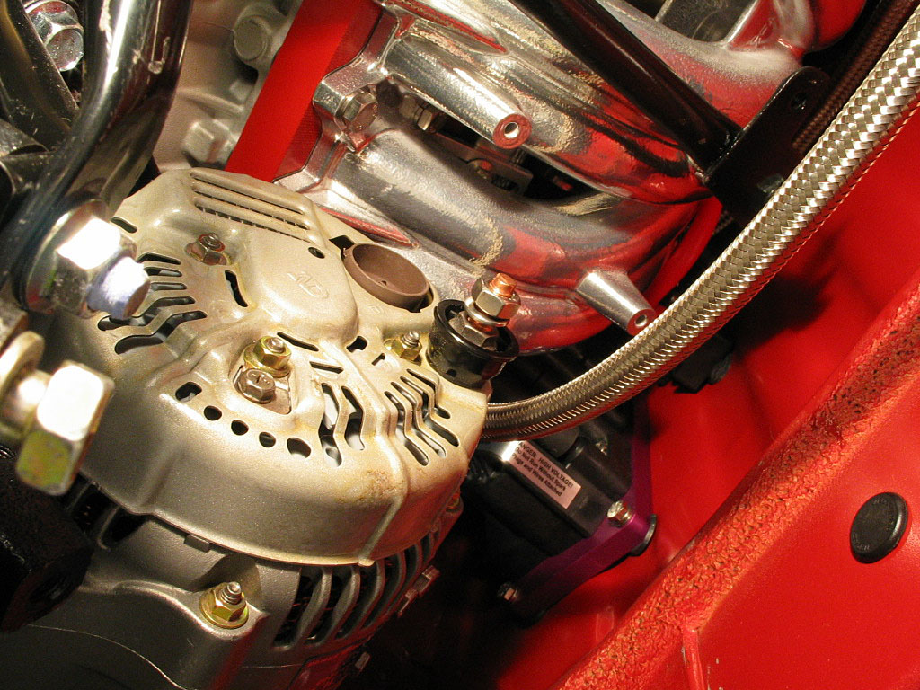
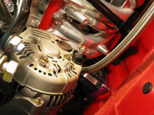
First, I cleaned off the main power cable's
ring terminal with a wire brush, then attached it to the alternator stud:

|
|
| |
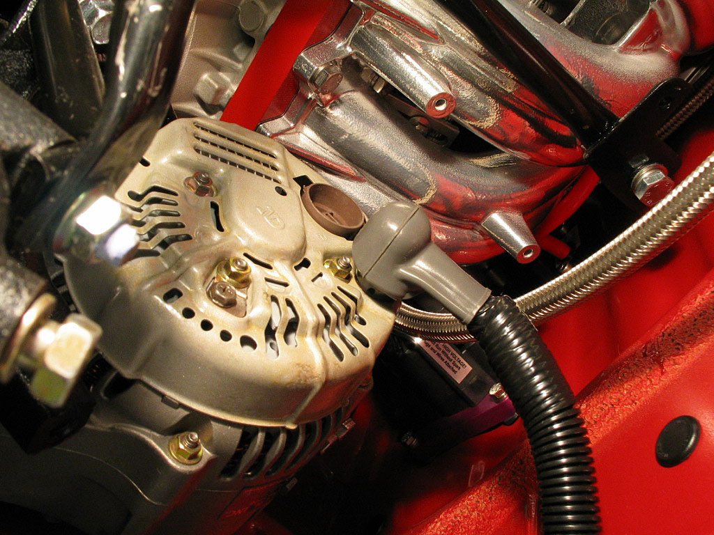
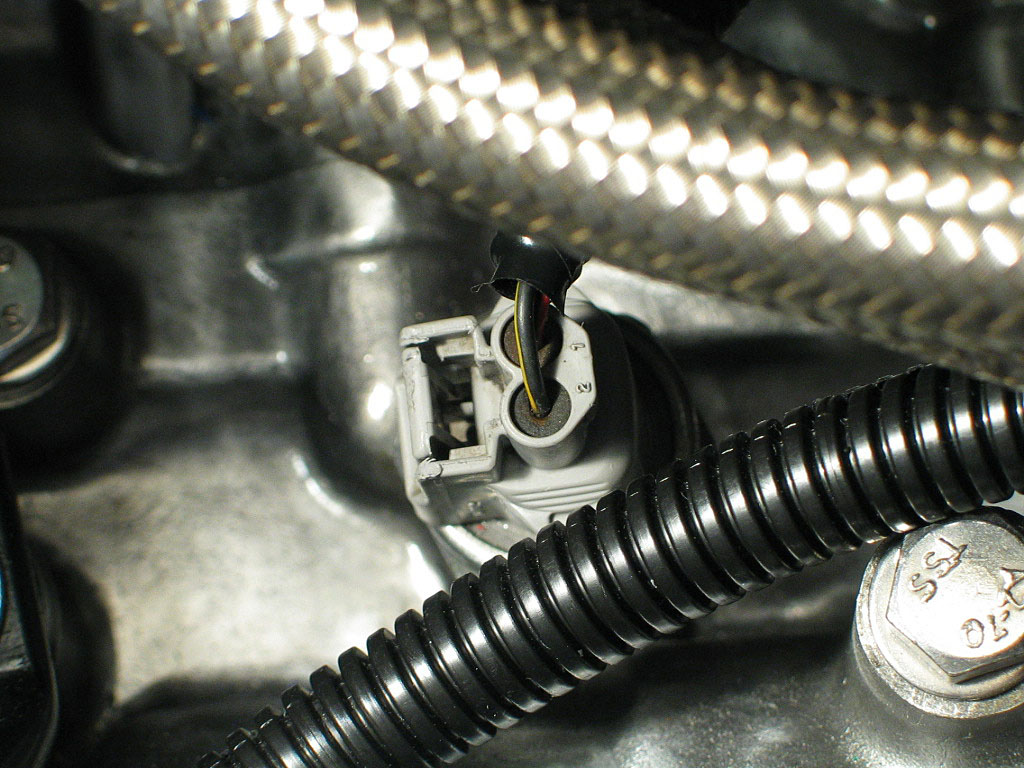
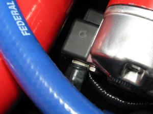
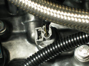
Next, I attached the alternator connector
plug to the socket:

Make sure to press the plug in tight.
|
|
| |
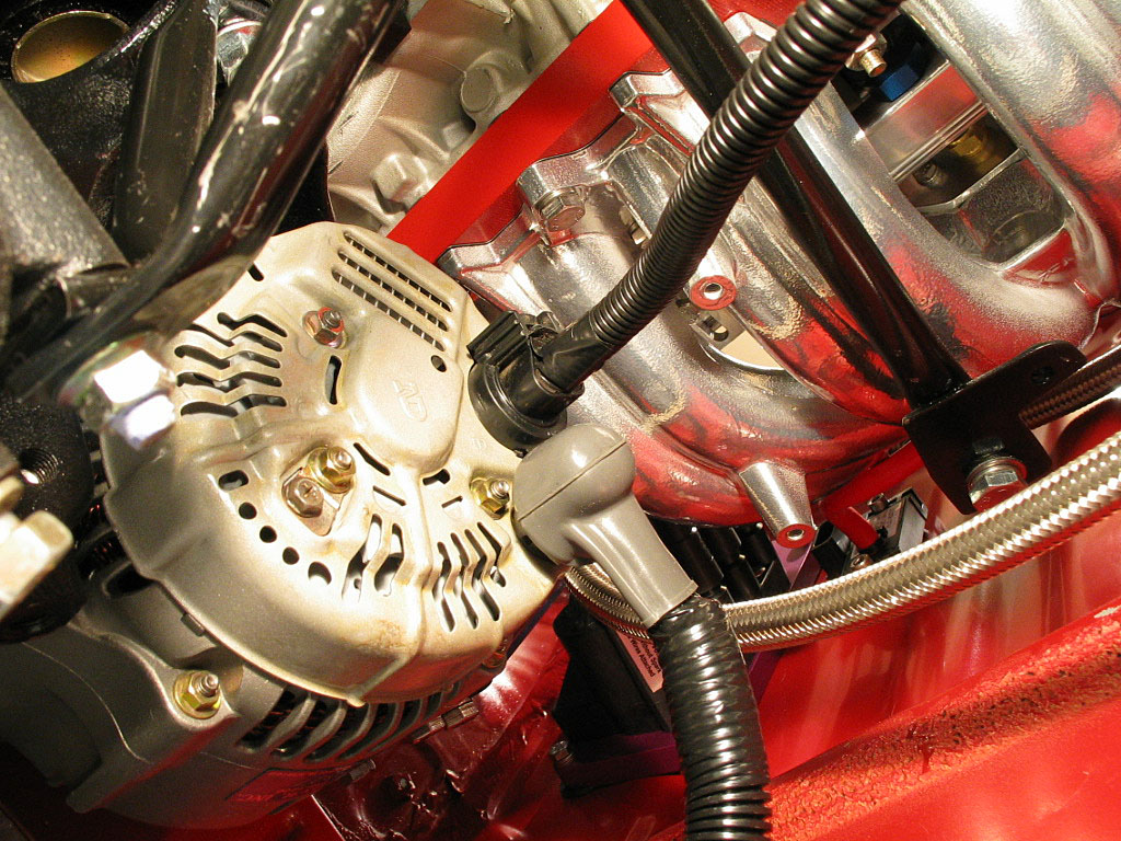
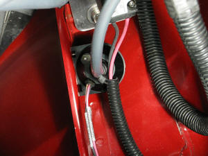
I attached the knock sensor lead to the
sensor, and bundled the wiring up within the alternator wire wrap:
|
|
| |
Next, I connected the two starter wires. One
attaches to the same stud as the heavy primary power lead, and the other
to a special connector. I tightened down the primary cable nut, then installed the
insulating cover:
|
|
| |
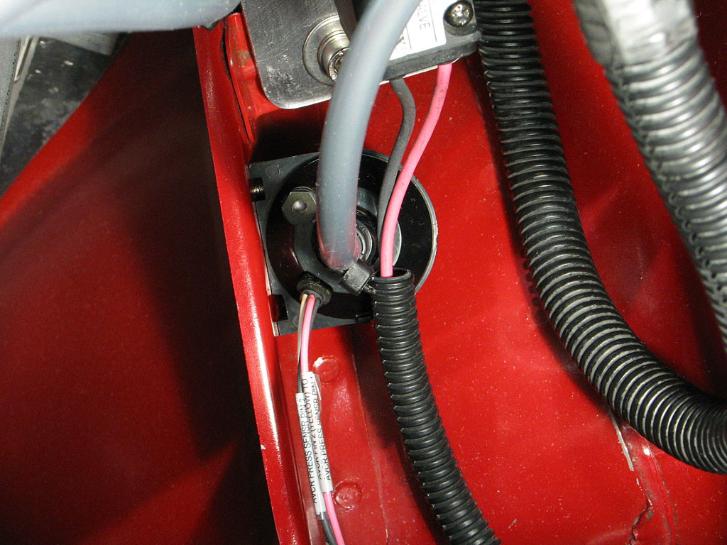
I slid some cable sheathing on the speed
sensor wires for protection, then attached the connector to the socket on
the transmission:

|
|
| |
I did the same for the backup light switch wiring:
|
|
| |
I discovered previously as I disassembled
the engine harness that the wires were intertwined, and you could not
untangle the various circuit wiring without detaching the pins from the
OEM socket connectors. The OEM connectors are not really designed to be
disassembled, as aftermarket connectors are. As a result, there's a
spaghetti of wires where they all intertwine, right near the fuse box.
Even with the reduced wiring in my harness, this was a mess.
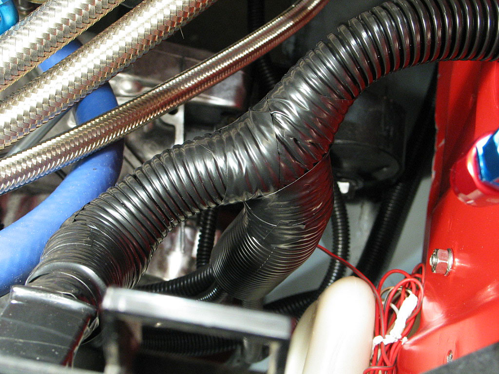
Once I had routed most of the circuits from the OEM harness, I wrapped
some addition cable sheathing around the wires at the junction where they
intersect, hoping I wouldn't need to rip it back apart in the near future
(the triumph of optimism over experience):

I will need to splice into the harness, but hopefully I can do that inside
the trunk.
|
|
| |
Continued on next page... |
|
|
|
|
|
Back to Start
Page
1
2 3
4 5
6
7
8
9
10
|
|
|
|
|