23 June, 2005
UNDER CONSTRUCTION
Installing the 3SGTE
Wiring the TECł and Sensors
I'm not sure these instructions will work for your car. I'm posting them in the hope they help somebody in their project. They are not gospel, they might even contain errors. Nobody's perfect. You are on your own.
So if you follow these procedures and burn up your ECU, your wiring harness, or otherwise damage your car, I'm sorry, but I am not responsible. Be careful, and get input from many sources. If you are not sure what you are doing, and you can't afford to make a mistake, take your car to a reputable speed shop.
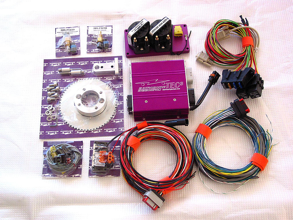
The TECł harnesses are terminated at the ECU end. While the sensors include nice GM-style automotive connectors, all of the other leads need to be spliced into either the stock sensor leads or other aftermarket connectors. I also decided to add an idle air controller valve (IACV) and a cam sensor for full-sequential fuel injection.
When it comes to splicing wires, there are opposing camps on which connection type is best. Crimped butt connectors can produce excellent joints if the the crimp is properly executed. Seamless connectors are recommended to prevent a "flattened" joint, which is usually suspect. Connectors are available for many types of finished joint, from simple un-insulated tinned copper to elaborate crimp-and-solder connectors with adhesive lined heat-shrink insulation. The latter are targeted for marine use, and cost roughly 10 times the cost of a simple butt connector.
Since automobile manufacturers universally use crimped connectors, it's a pretty good sign that a properly made crimp connection is a solution of choice. (Please don't start a flame war on that statement!)
For most of the splices, I used uninsulated seamless crimp connectors from 3M, with polyolefin heat-shrink tubing for insulation. I also used a ratcheting-type crimp tool to get consistent results.
The Electromotive TECł manual is an excellent source, as the circuits are described in detail. The BGB provides information about the circuitry on the 3S-GTE, and the BGB Electrical Wiring Diagram addendum has the circuits all laid out in color. An excellent guide. And Ricky Benitez has an excellent write-up on installing a TECł in an MR2.
Unfortunately, none of these resources covered everything, as they all had a slightly different focus, just as this guide won't work for a different configuration. However, the combination of all of the resources made me comfortable in proceeding.
It's really a matter of being careful and organized as you proceed. Trying to get this done in a hurry is asking for trouble. You need to check and double check everything. And ask questions when you aren't sure. I asked plenty of questions of Troy, Ricky, and Electromotive Tech Support.
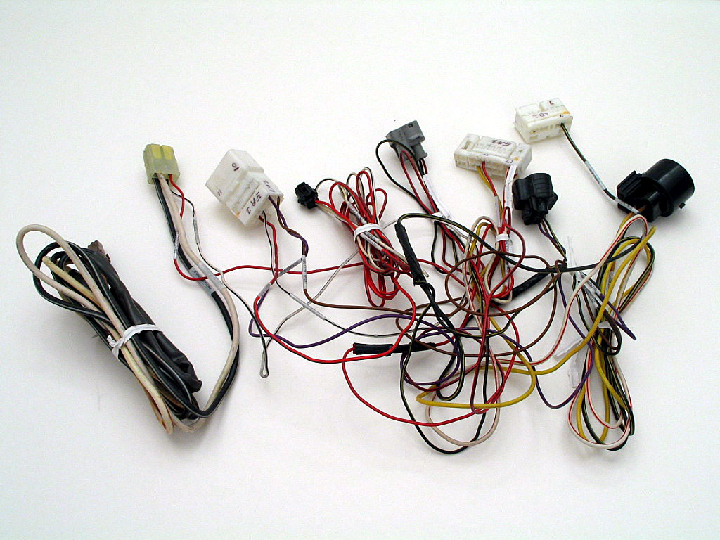
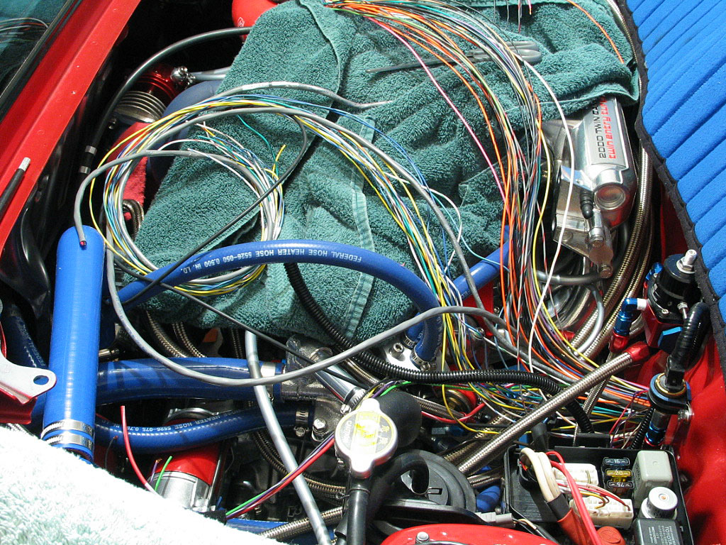
It's still a bit tangled, but that can't really be avoided unless you want to re-splice the factory connectors to eliminate the intertwined wires. Without the proper tools, that's risky, as you could end up with a non-working harness. Besides, eventually this mess will be hidden inside black plastic sheathing.
As I disassembled the OEM harness, I took photos of the OEM connectors, along with their associated wires.
I'd also added some components that weren't strictly necessary, so the job had become more complex in the process.
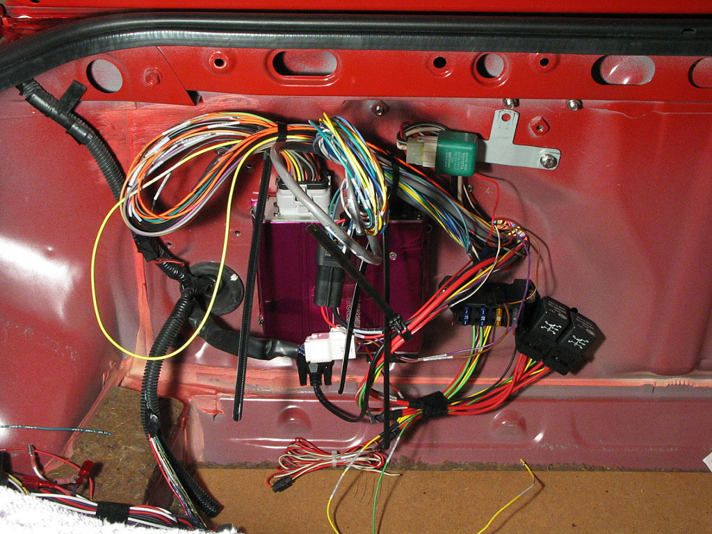
My plan was to install run the wires to their locations, get the car running, then try to clean up the mess. It would be much simpler to troubleshoot any electrical problems when the wiring was exposed than to trace it down after everything had been buttoned up. While I took some steps to neaten things up, they were simply to safeguard the wiring, and were reversible.
The biggest constraint was the location of the bulkhead holes for the wiring harnesses.
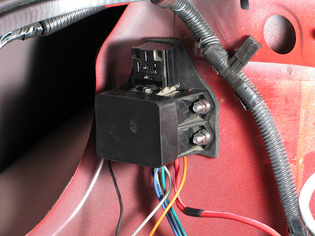
The starter relay was relocated to a new location.
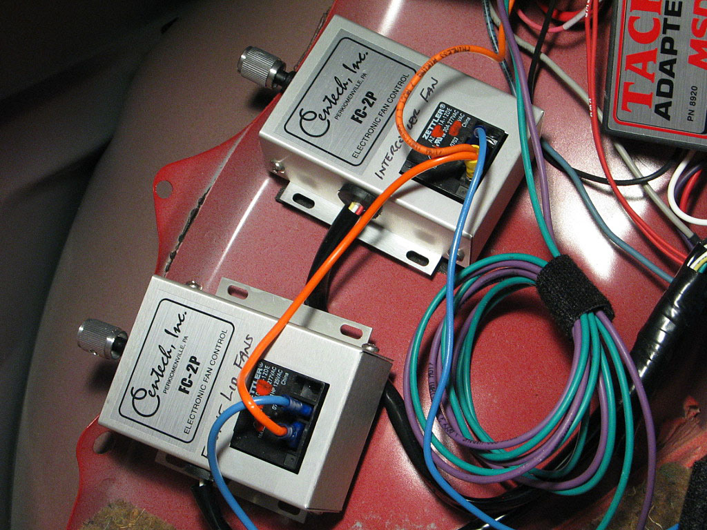
The controllers will will cycle the fans on and off depending upon the air temperature readings from a couple of temp sensors.
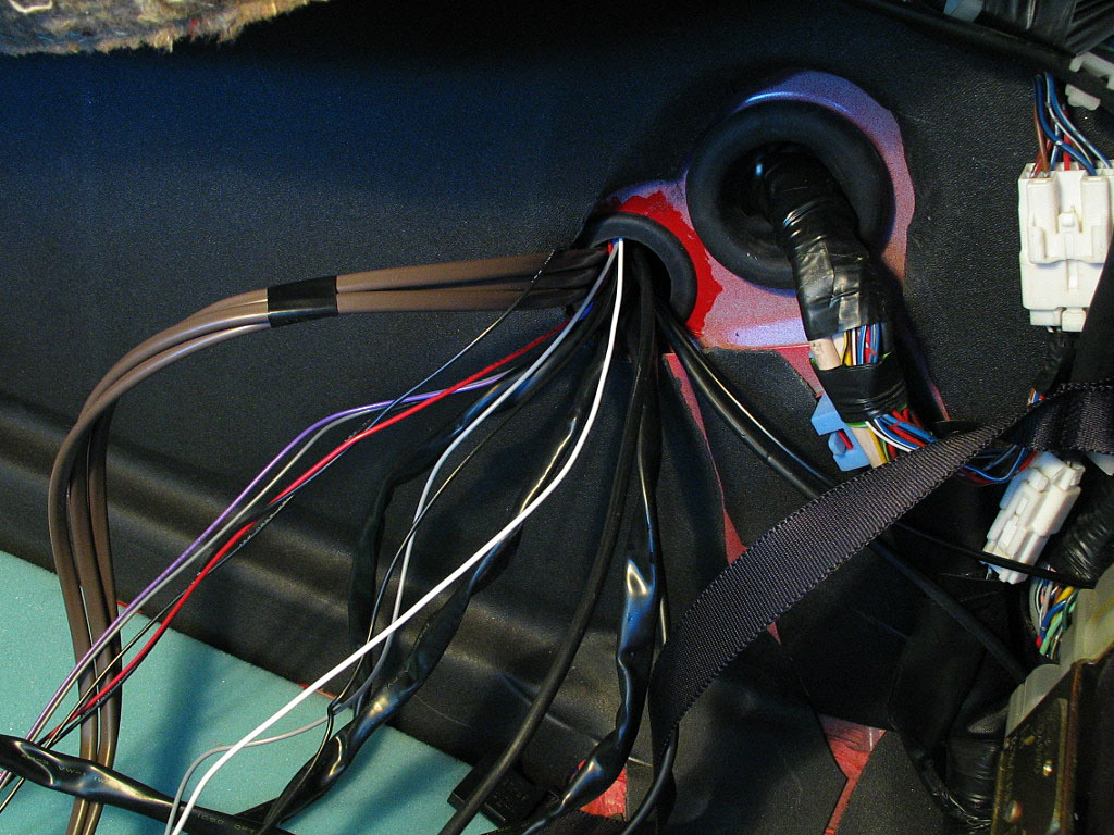
First, I had to determine the general target location of the wires -- which ones went through to the cabin, which ones went to the right side of the engine bay, which ones to the left. This also showed me which wires needed to go through which bulkheads.
I found that the hole through the forward bulkhead (into the cabin) was not really adequate, so I enlarged a smaller thru-hole located there, previously used for the engine lid latch release cable. I opened it up to 1˝" in diameter with a hole saw and installed a rubber grommet of that size to protect the wiring.
I could see that my original plan to install most of the engine components before running the wires was now going to slow me down as I tried to find a clean way to route all of these wires to their targets. On the positive side, the engine bay was still much more accessible than the one in a stock MR2 Turbo.
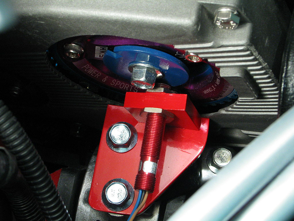
The crank sensor is secured into its bracket with a single set screw. I replaced the stock screw with locking screw that hopefully wouldn't back out later:
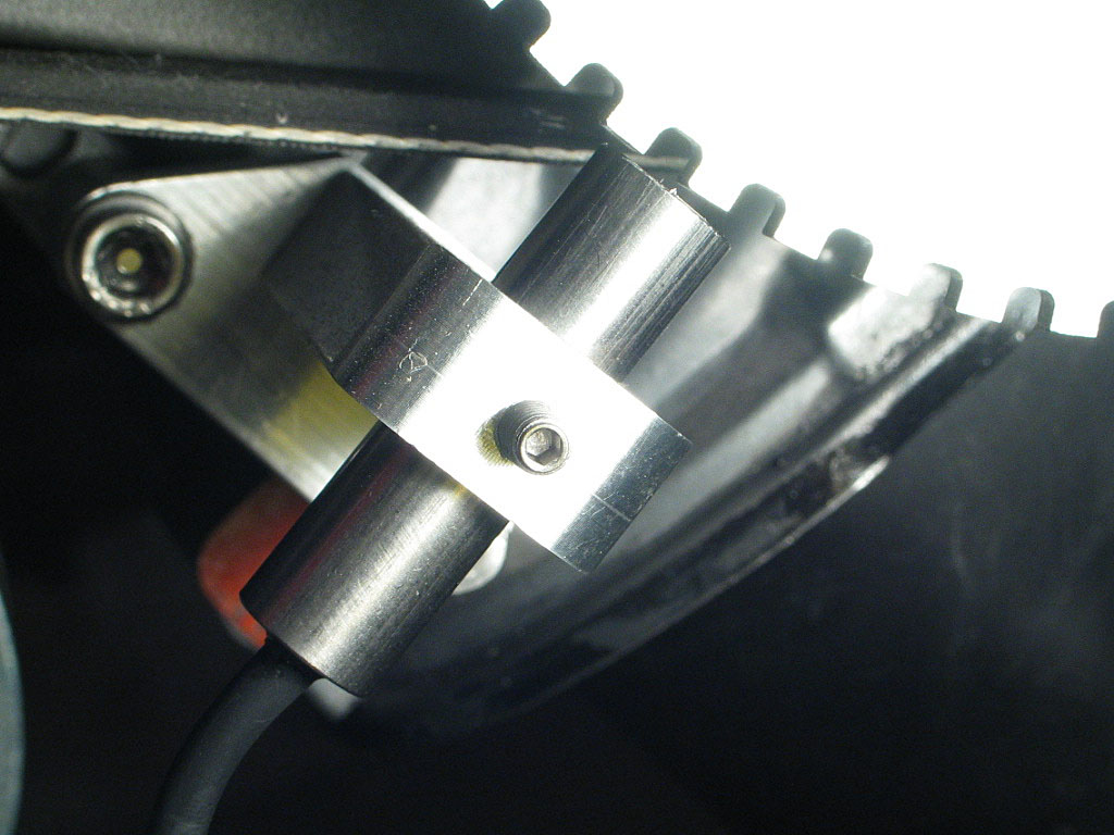
I noticed that the sensor wasn't exactly perpendicular to the trigger wheel centerline. Since the air gap between the two is pretty critical, that needed to be corrected.
I tried rotating the sensor bracket with the mounting bolts loosened, but it didn't really have much play in it. So I removed the mounting bracket and disassembled it. By elongating one of the holes, I was able to rotate the sensor mount on the base plate enough to achieve perfect alignment:
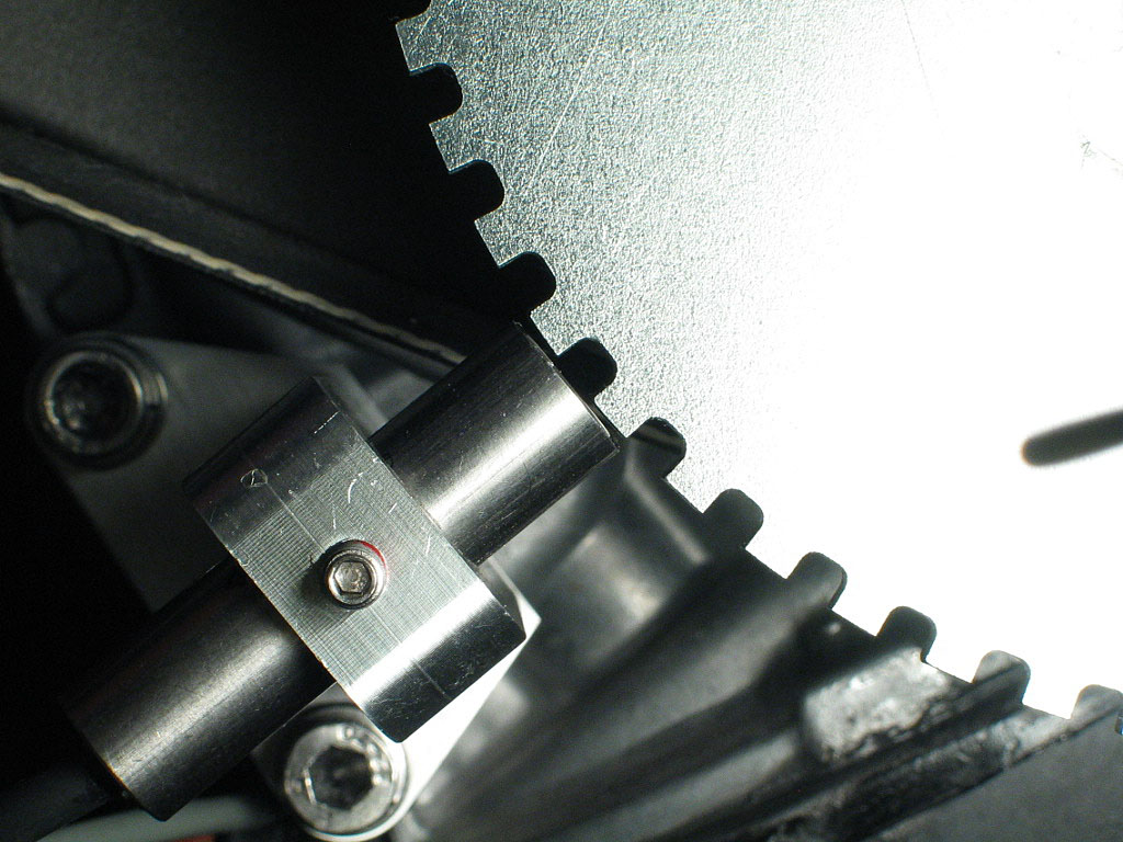
Now the sensor can be adjusted for air gap.
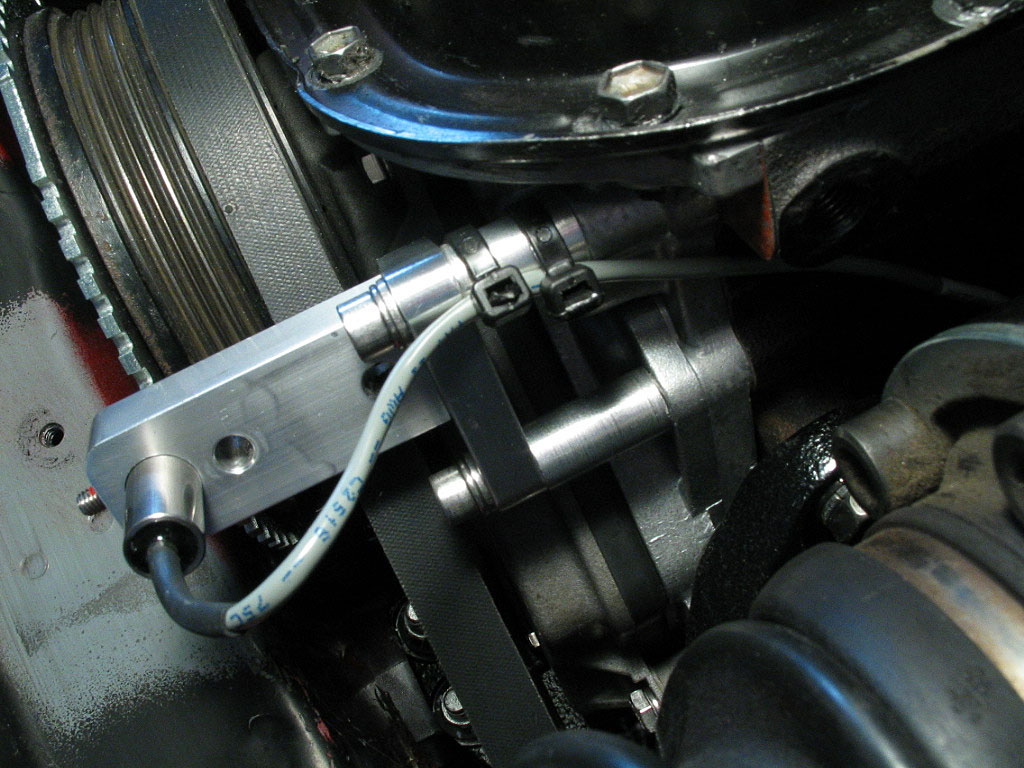
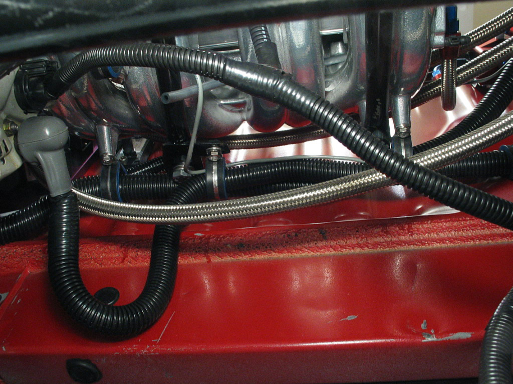
...I snaked the cable up under the alternator bracket's lower mount...
...then ran it through a lined cable clamp I'd installed on the intake manifold:

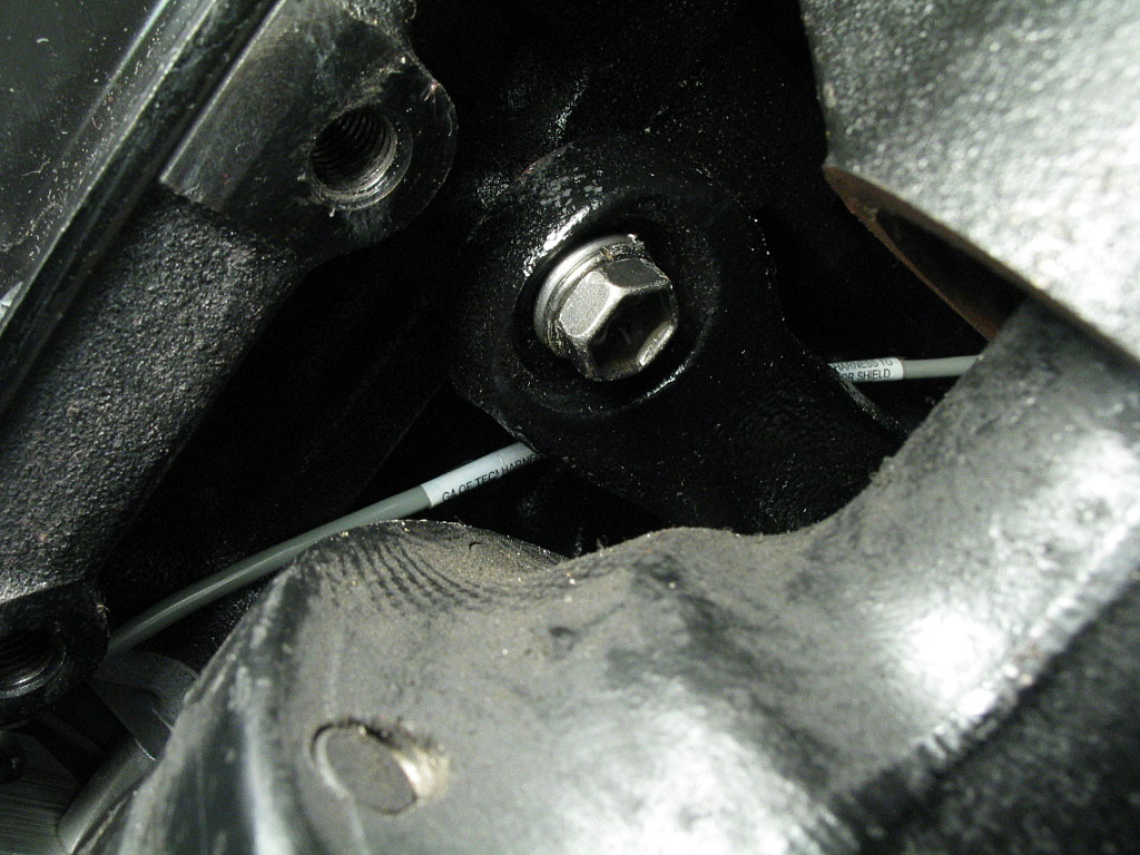
The crank sensor had a long cable with a WeatherPack connector on the end that would reach into the trunk.
This, too, would require exact alignment later.
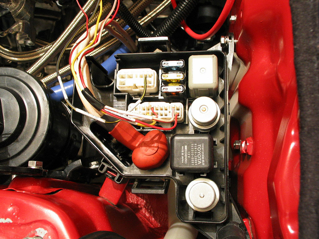
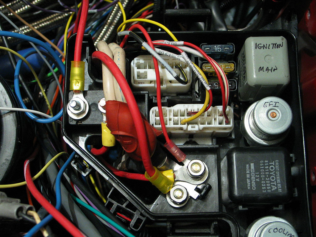
I detached the fuse box from it's mounting brackets and flipped it over. The wire I was targeting was the Black w/Orange wire leading from the ignition switch to the Ignition Relay:
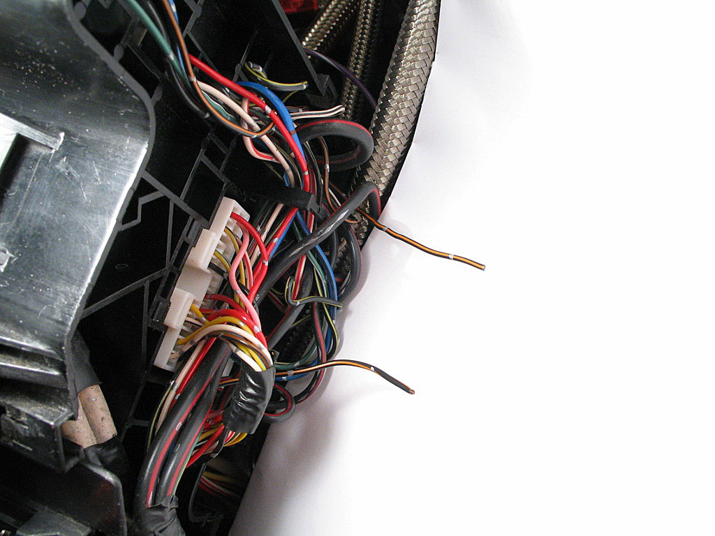
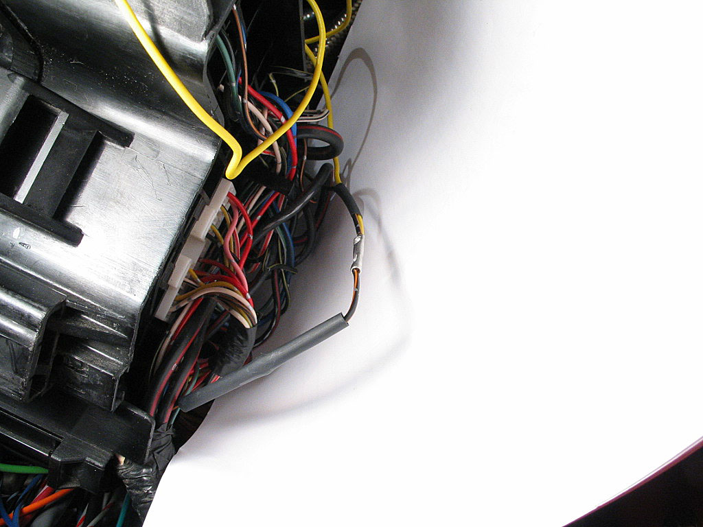
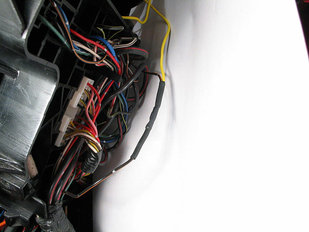
The yellow spliced wire can now be used for a number of circuits that need a switched +12V signal, but only for low-amp circuits.