Last Updated
23 June, 2005
 

      Back to Start                Page      1  2  3  4  5  6  7  8  9  10    


UNDER CONSTRUCTION

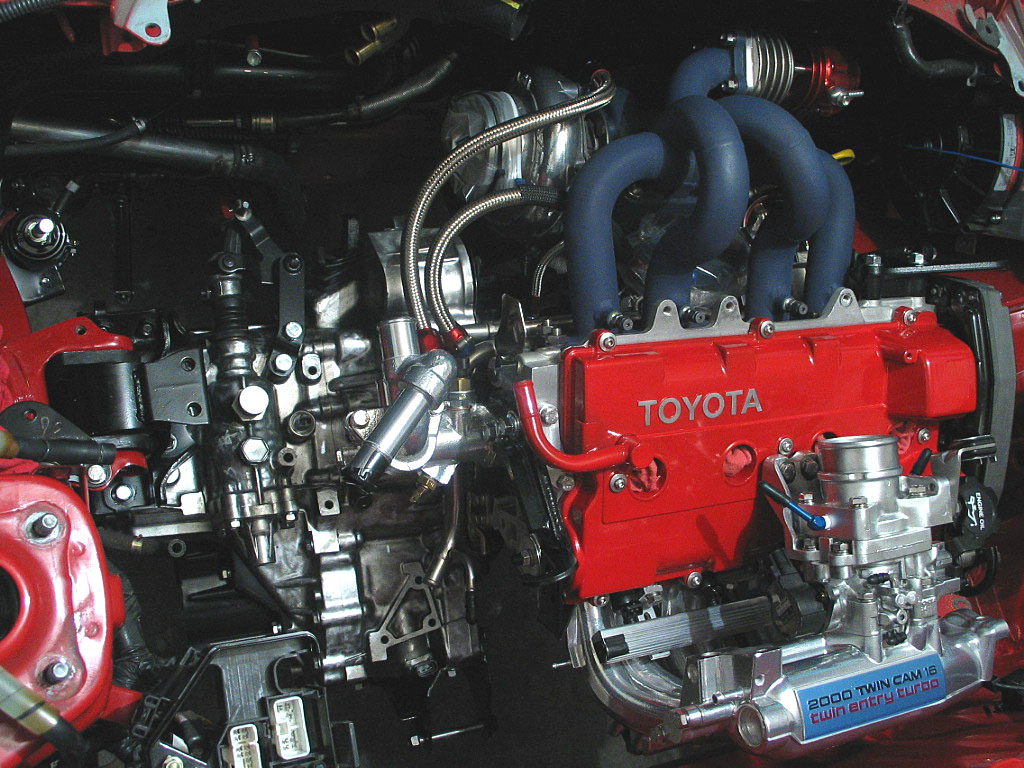
Installing the 3SGTE
 

  Before beginning the actual hoisting of the engine, trust me when I say that this is definitely a two-person job. Yes, it can be done by one person, but it will take much longer to complete and annoy you far more than it's worth. Often that second pair of hands is only asked to align the motor as it is being hoisted, or perhaps raise the hoist a little, but without that help the task becomes tedious. And the safety risk of working alone moving heavy equipment cannot be ignored.
 
 
  With the motor in position, I attached the chains to the lifting hooks. A point here is that both legs of the chain or sling should be pretty even. No matter how I've done it, the alignment is never perfect, but your goal here is simply to get the left and right mounts attached. After that, things become much easier.
 
 
  Toyota uses rubber cushions on the isolators where they fit into the body mounts. Here's a shot of one:
Click to enlarge
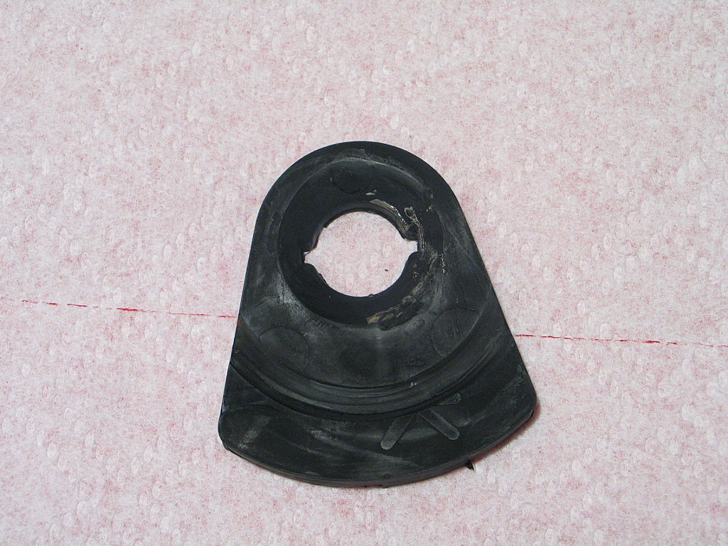
These parts don't appear in my copy of the Electronic Parts Catalog (EPC), so I don't know what Toyota calls them.

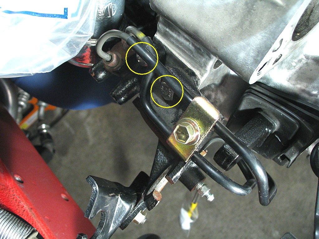
The left- and right-hand side cushions are shaped differently. The right-hand side cushions have a large "L" cast into the rubber. Don't make the same mistake I did and try to use these on the "left" mount, as logic would seem to dictate!

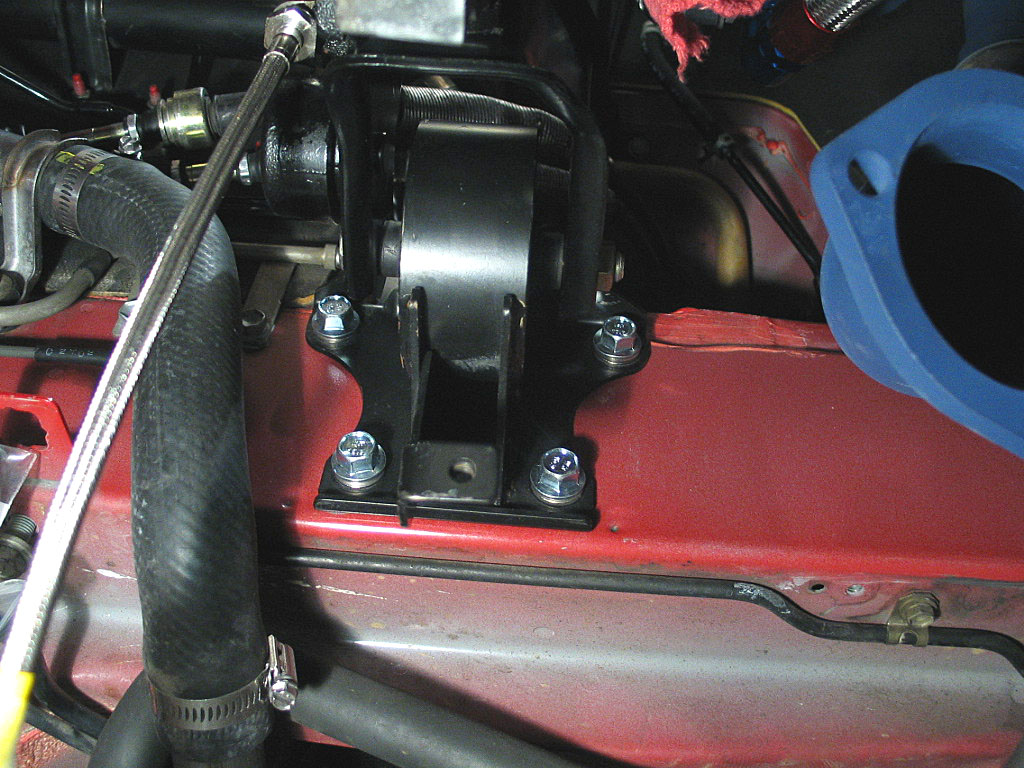
The cushion above has a "K" cast into the rubber, and fits the left-hand mount. The concave area around the center hole fits over the isolator, and the flat side fits against the body bracket. The notches help keep the cushion aligned on the isolator. Use plenty of soapy water on the side that meets the body bracket to help things slide into position.
 
 
  With the left-hand isolator installed, I dropped the right-hand isolator (not yet attached to the motor) into place in the body bracket and slid the through-bolt into place.
Click to enlarge
 
 
  From underneath the motor, I aligned the two studs that extend from the isolator, and slowly lifted the motor over the studs, until I could spin on the nuts.
Click to enlarge
 
 
  At this point, the motor was supported by the left- and right-hand mounts, and I could detach the hoist:
Click to enlarge
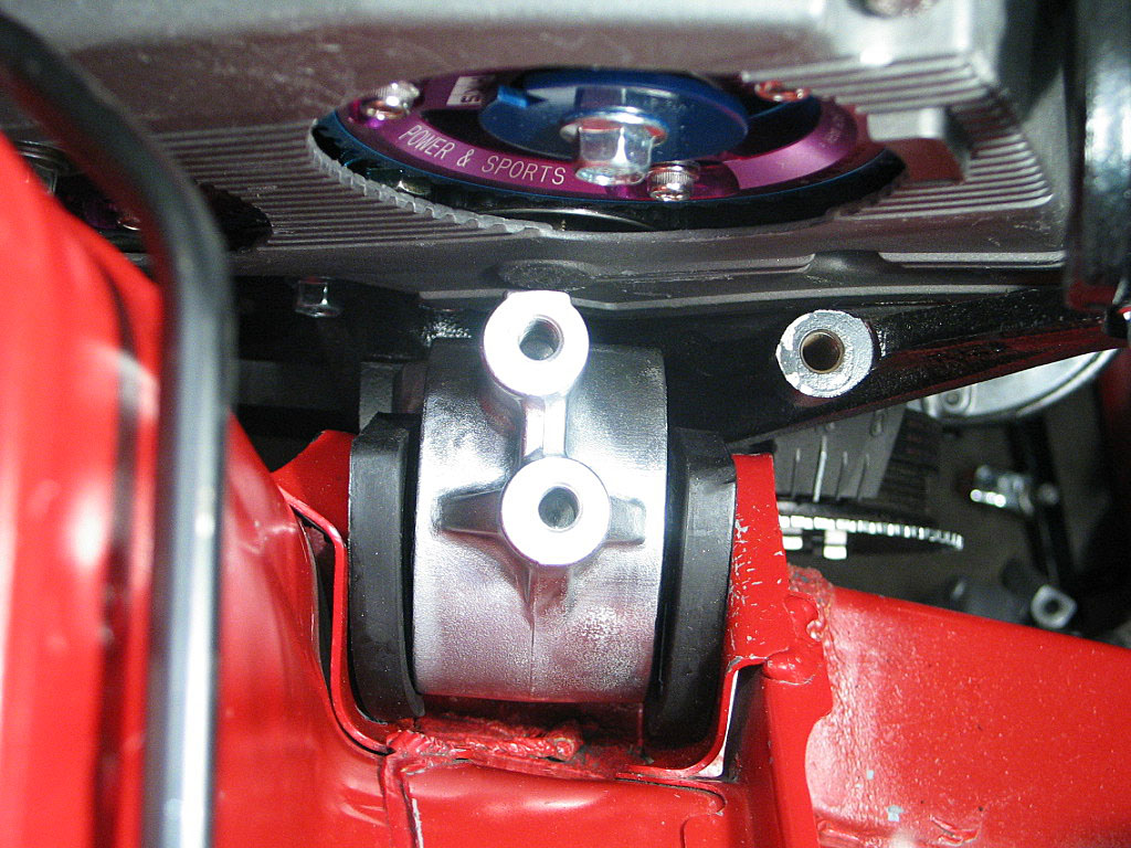
The mounting bolts were still just finger tight, so that I could easily install the front and rear mounts and then torque everything to spec.
 
 
  This is the point at which I should install the A/C compressor, because the motor can be rocked a bit to make fitting the unit a bit easier. Unfortunately, it turns out the eXtremeBoost downpipe blocks the A/C compressor, something I should have measured with the motor out of the car:
Click to enlarge
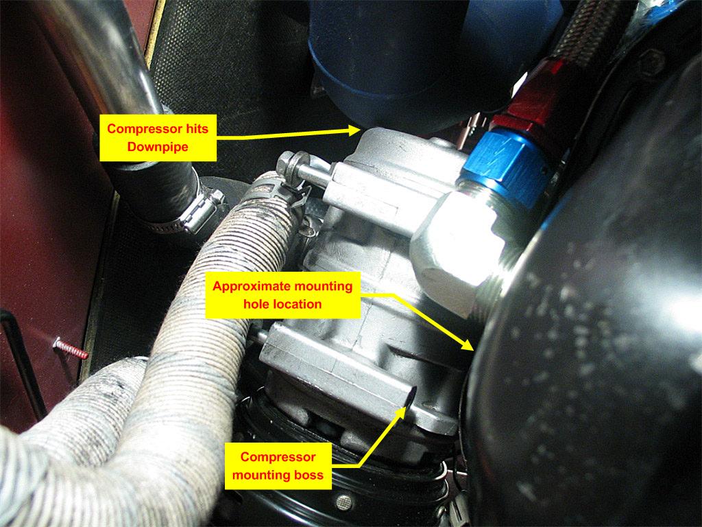
Wasn't mentioned to me when I bought the turbo kit, but that's just old news at this point.

For now, I'll remove the compressor until I find a solution.
 
 
  Take the clutch slave-cylinder assembly, and mount it to the transmission case using the two 12mm bolts, as shown below:
Click to enlarge
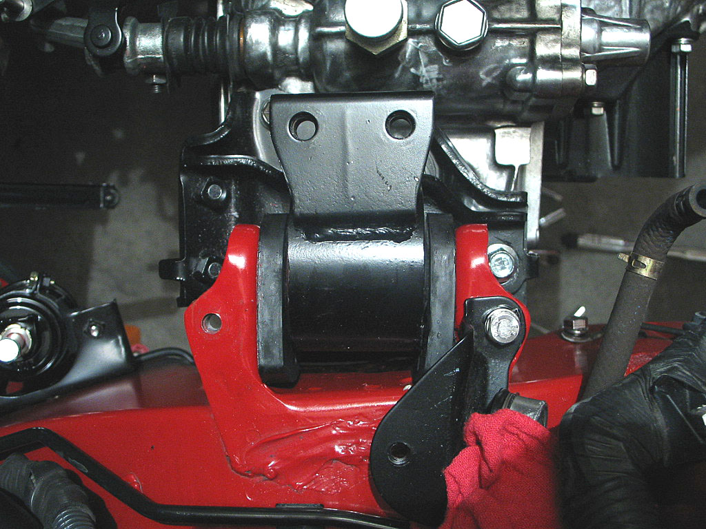
The longer bolt goes towards the left side of the car (to the right in the photo above). Just finger tight at this point.

NOTE: make sure you install the clutch rod into the slave cylinder before attaching the bolts:
Click to enlarge
I forgot the rod and had to pry the clutch lever away from the slave cylinder to slip it into position:
Click to enlarge
The really hard part was getting the dust boot over the slave cylinder -- no room to work once it's installed.
 
 
  From underneath, install the front mounting bracket to the transmission case. It sits on top of the clutch cylinder bracket, and attaches with two 14mm flange-head bolts.
www.highandtight.com
Torque these two bolts down, but be careful and remember you are working with aluminum threads on the case!

When you are done, you can tighten the two 12mm clutch cylinder bolts from the top of the motor.
 
 
  Install the front engine isolator to the frame, using four 14mm flange-head bolts:
Click to enlarge
Torque these down to BGB spec.

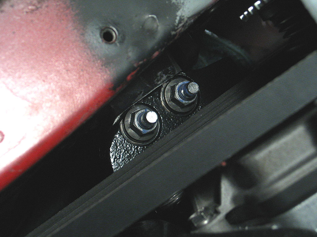
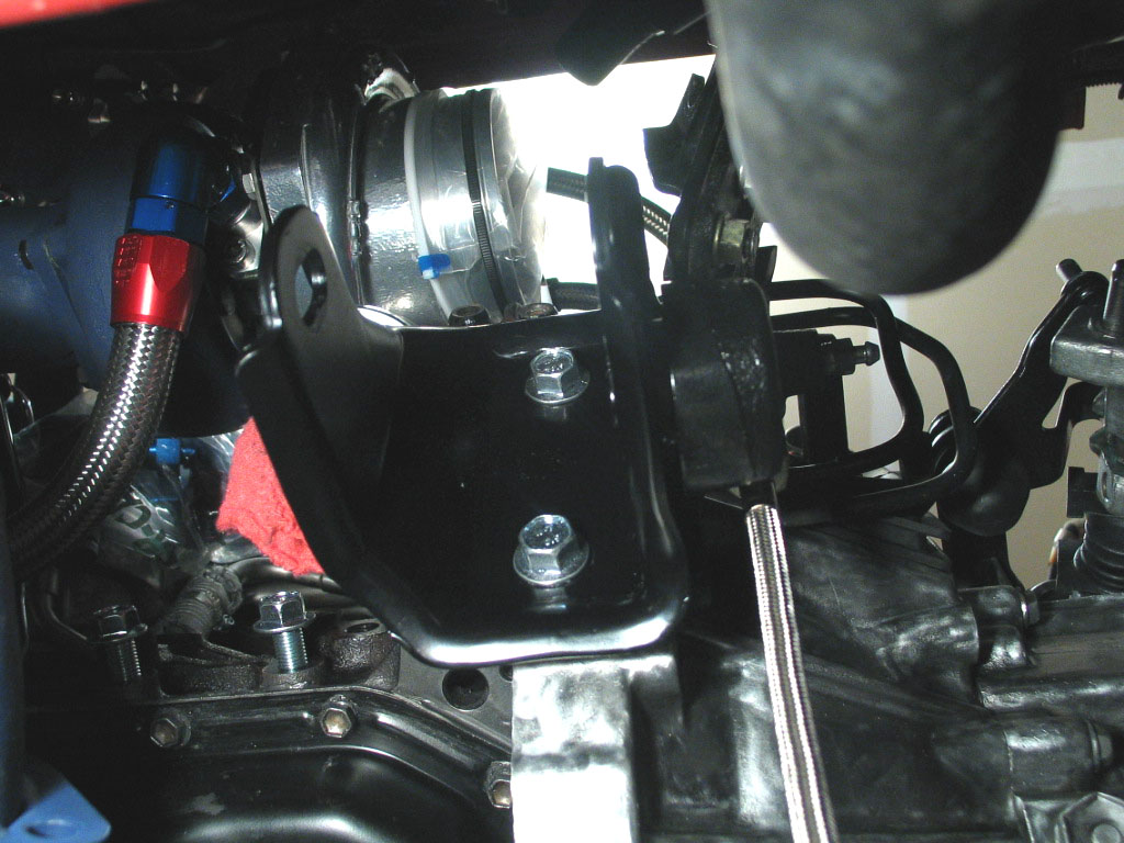
Slide the through-bolt in place, rotating the engine as necessary, and attach the nut. Don't tighten this down yet.
 
 
  The right-hand engine mounting plate is attached with three 14mm flange-head bolts:
Click to enlarge
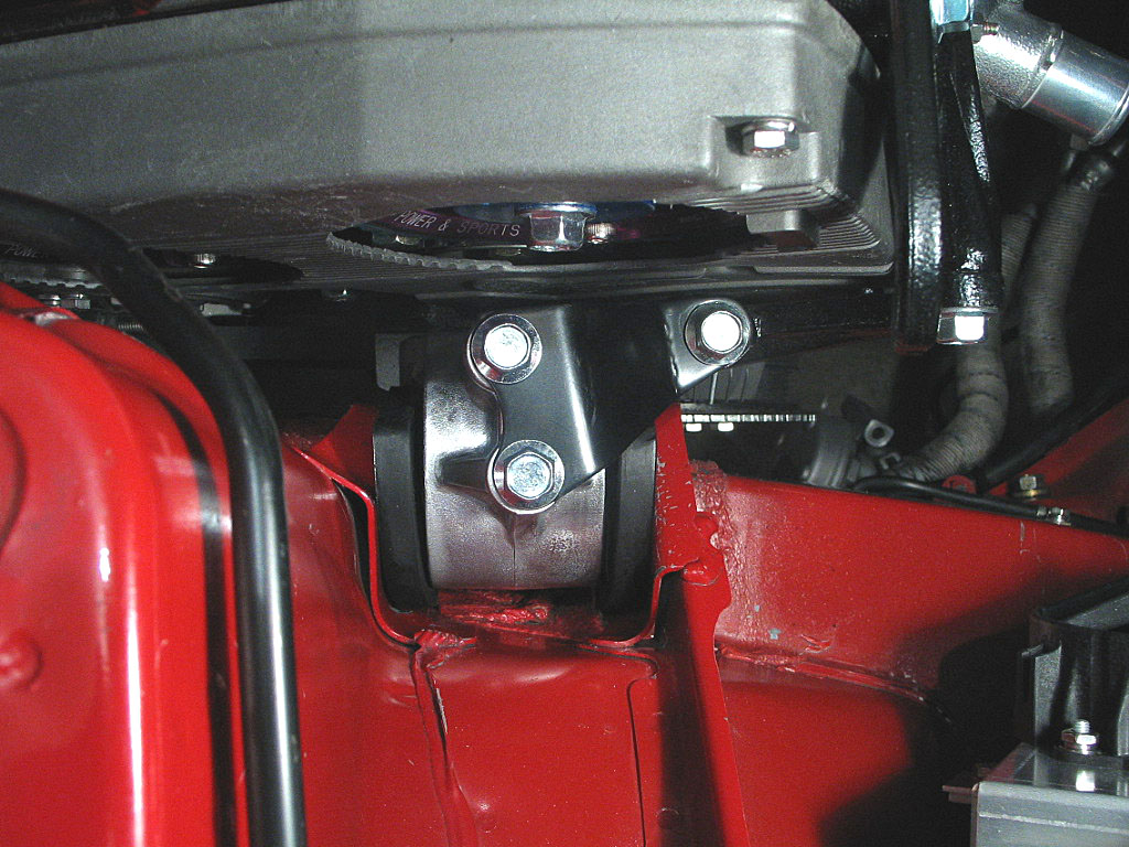
Torque these down to spec, again being mindful that two of them are threading into aluminum.

Torque the through-bolt to spec. On the underside, torque down the two 14mm nuts onto the mounting studs.
 
 
  Here's the left-hand mount:
Click to enlarge
Tighten the through bolt to BGB spec.
 
 
  I installed the large heat shield, which I had removed when replacing the fuel tank hoses.
Click to enlarge
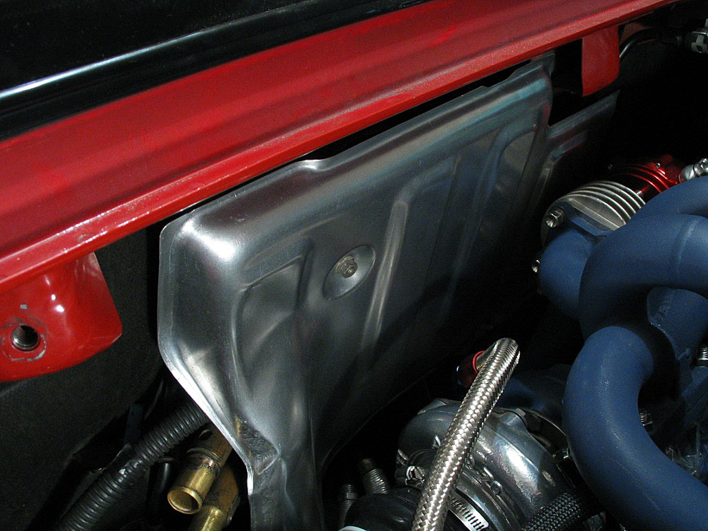
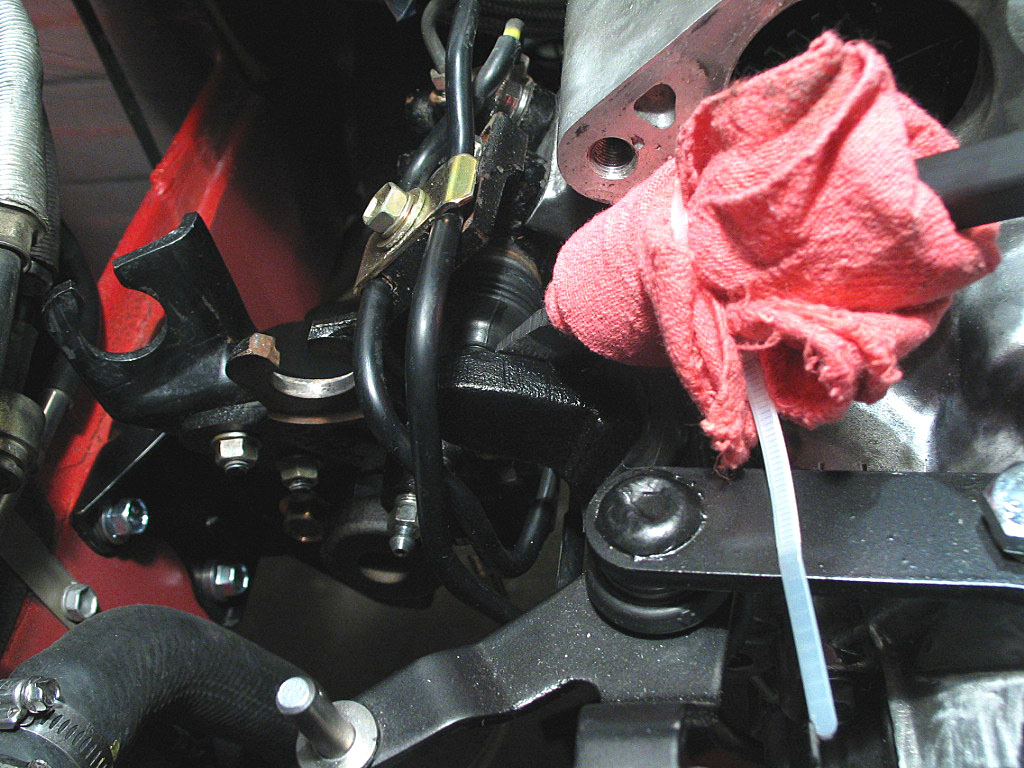
Unfortunately, the downpipe on my turbo would not clear one of the heat shield mounting studs for the smaller shield:
Click to enlarge
I had to cut about ½" off the end of the stud. And I would need to fabricate a replacement for the small heat shield, as it was designed to prevent heat from the turbo and exhaust manifold from reaching the fuel tank. Now there is a large hole there.
 
 
  I was replacing the stock hydraulic hose for the clutch slave cylinder with a stainless braided hose. Time to reconnect it to the clutch line:
Click to enlarge
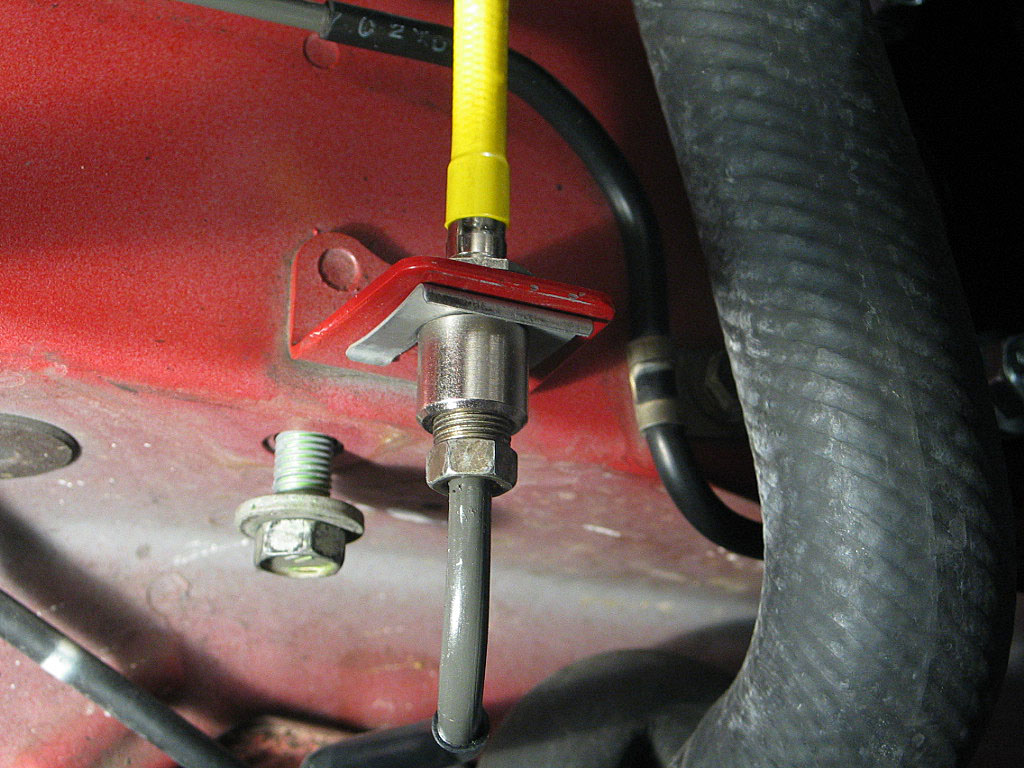
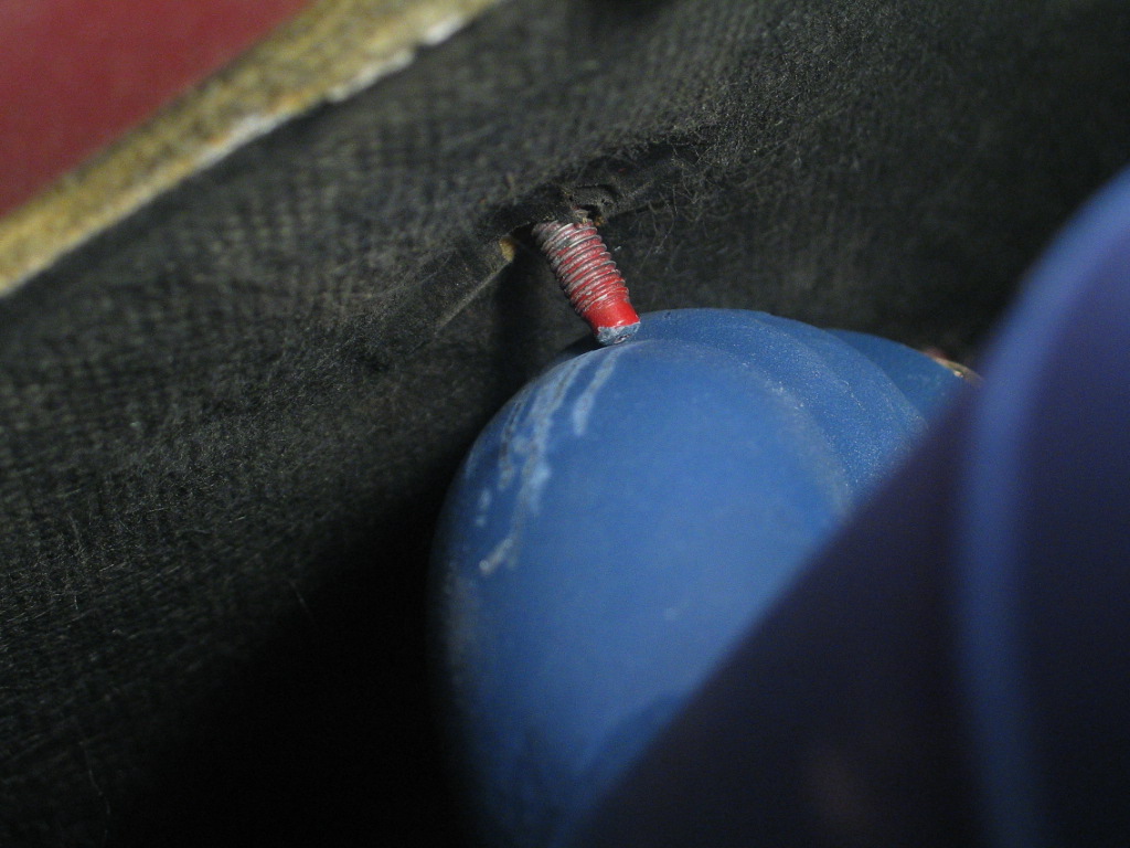
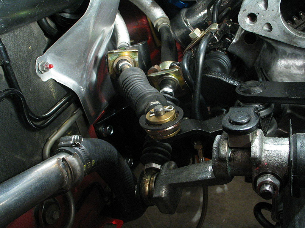
The U-clip secures the hex-shaped collar into the bracket. You'll need a 12mm flare-nut wrench to tighten the connection.
 
 
  The two shifter cables need to be secured to the mounting bracket with the U-clips:
Click to enlarge
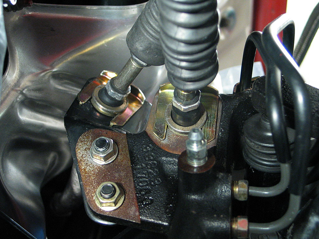
The cable on the left in the photo goes to the top pin on the shift control arm.
 
 
  I had purchased a set of brass shifter bushing to replace the rubber OEM bushings. These came from ClubMR2:
Click to enlarge
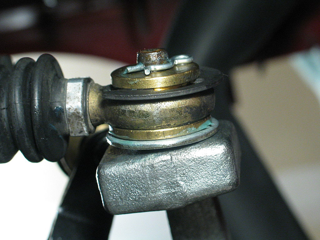
The photo above shows the lower cable end. You need to retain one of the spacing washers from the stock cable end installation. Then the bushing, the cable end, and finally the locking pin. I used a little Magnalube on the pin and bushing.

Even though the cable end appears to be slightly cocked, you'll find that the mating surface on the lever arm is cocked at exactly the same angle.
 
 
  The top cable doesn't need a spacing washer:
Click to enlarge
Install the the bushing, the cable end, and the locking pin, in that order.


Continued on next page...


      Back to Start                Page      1  2  3  4  5  6  7  8  9  10