23 June, 2005
UNDER CONSTRUCTION
Installing the 3SGTE
Don't tighten the through bolt yet, just thread it in a few turns.
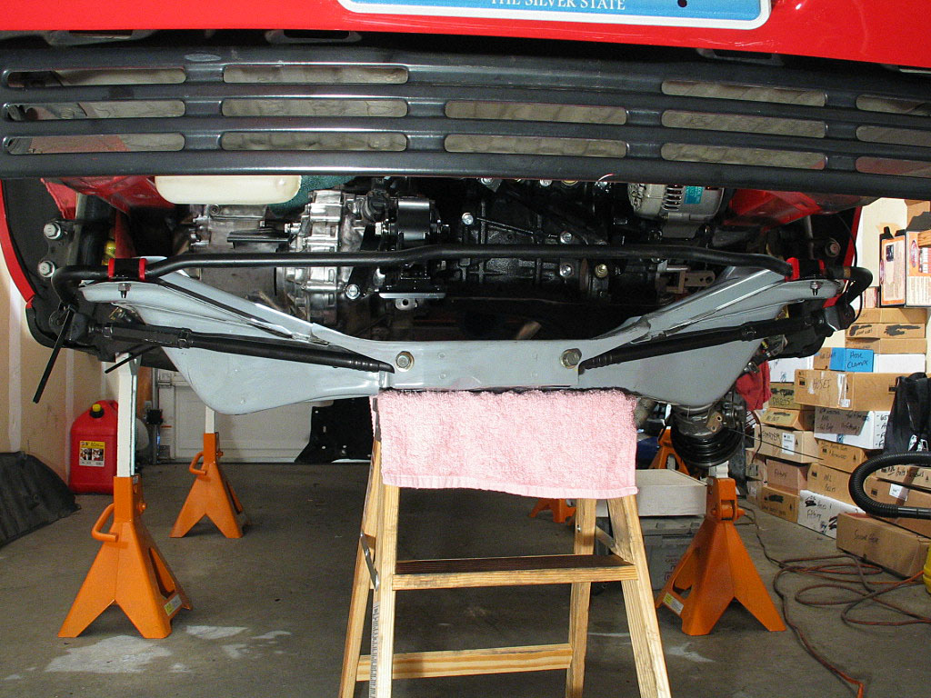
I installed the bolts that secure it to the body, first on one side then on the other. I then torqued them down evenly.
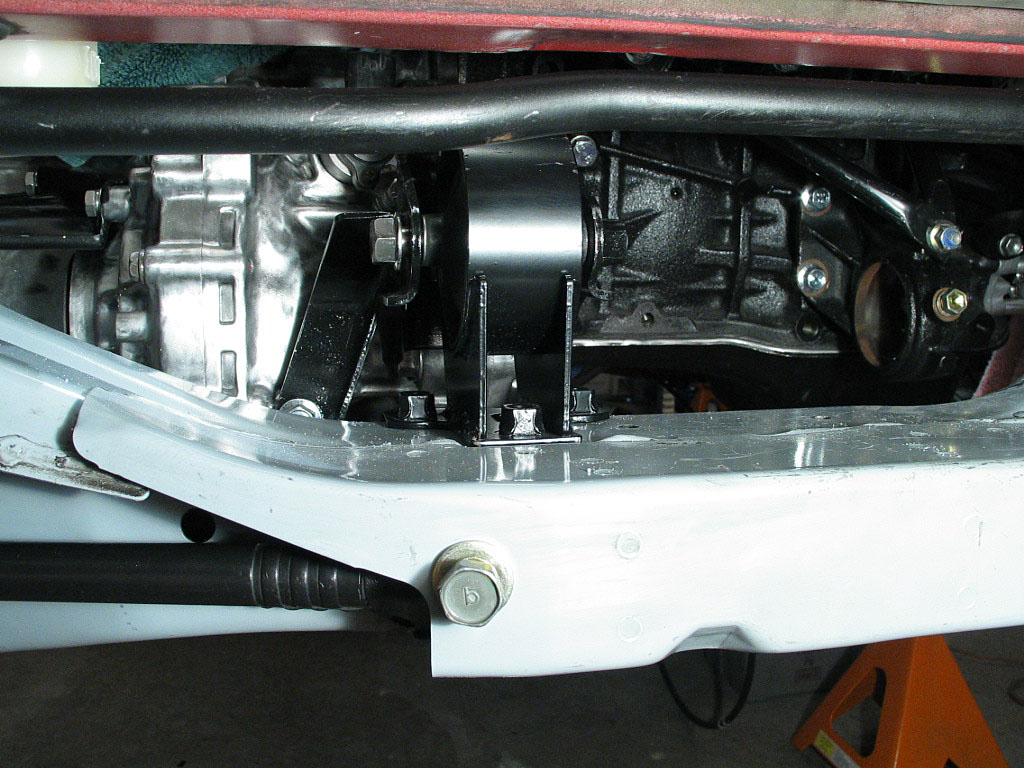
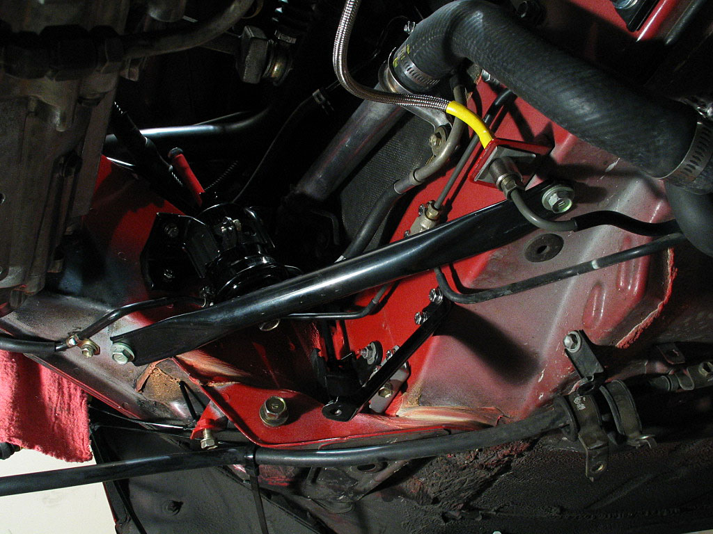
Install the three bolts through the crossmember and into the mounting plate. Torque them down evenly.
This would be a good time to reinstall the driveshafts, hubs, and rear suspension components. I was trying to find someone to press out the stock bushings, so I moved on to other components.
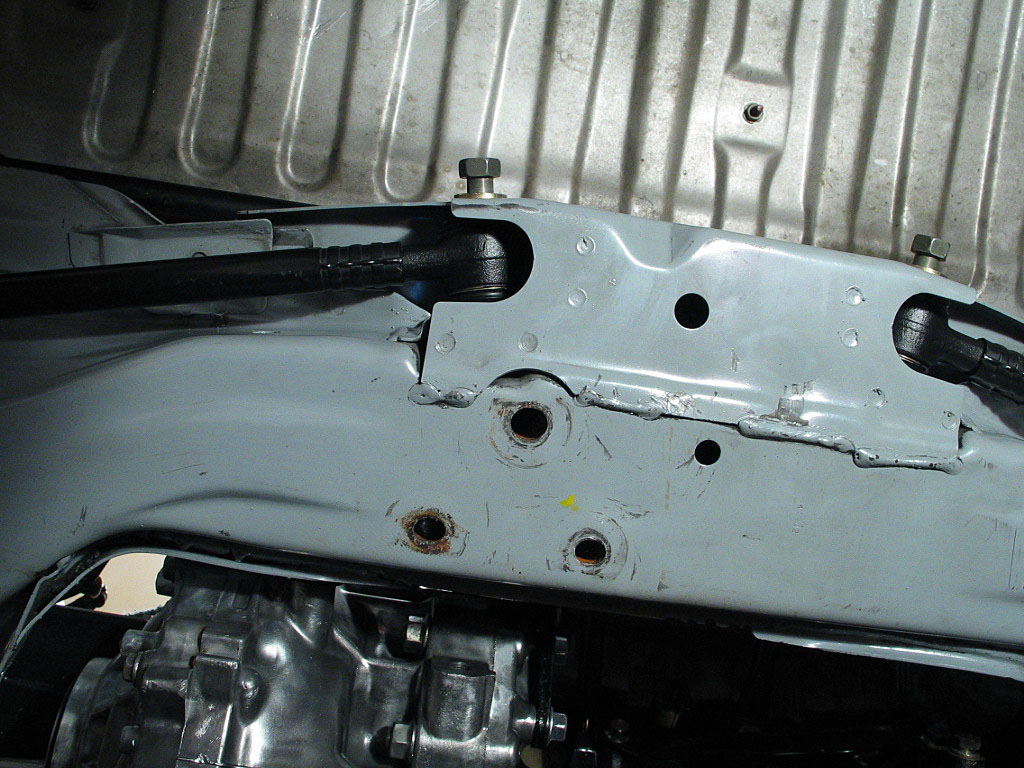
These tend to rust through, so be prepared to replace them.
Attach both of them with the 14mm bolts, and torque them down to spec.
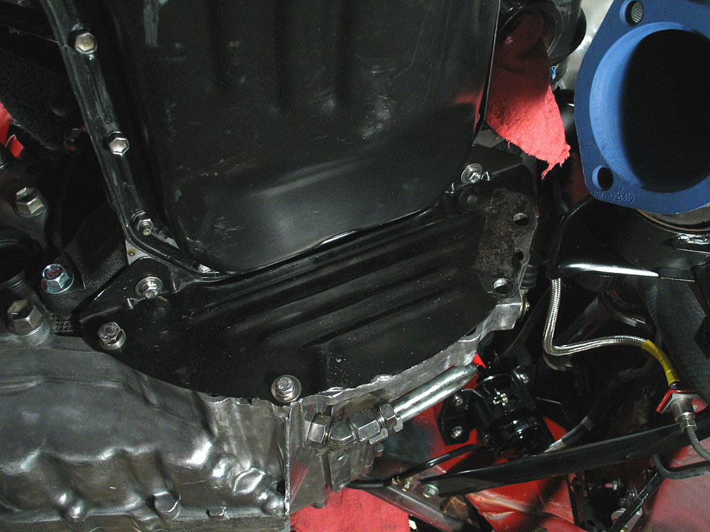
Two 10mm bolts attach to the bottom of the engine block, one 12mm bolt and one 10mm bolt attach to the clutch housing. There are two 14mm bolts located on the upper clutch housing, and these are accessed from the top of the motor. The remaining bolts secure the engine stiffener bracket, sandwiching the cover in between.
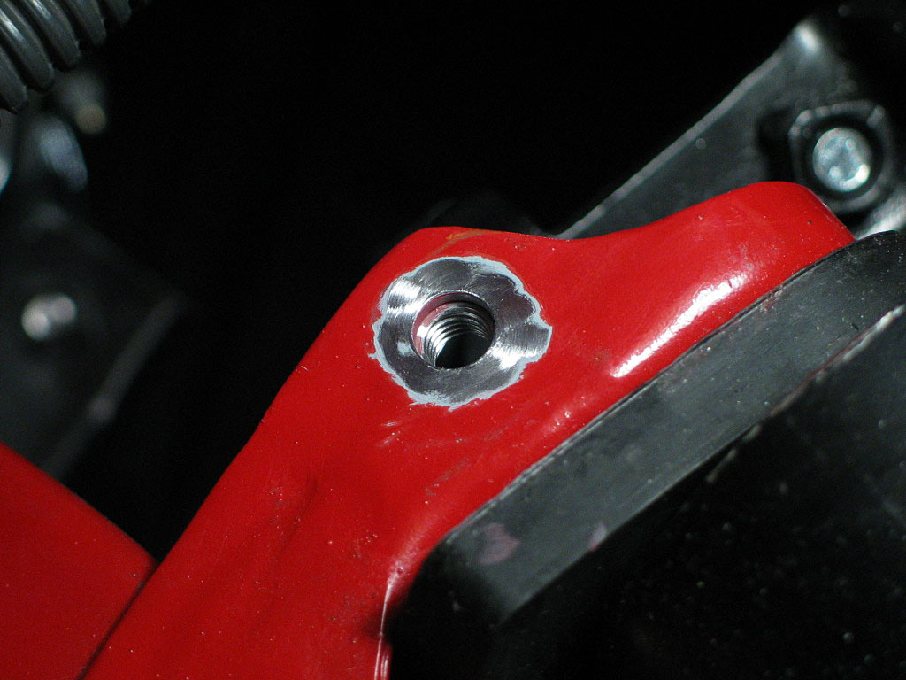
The third bolt attaches to the engine block, just above the rear of the oil pan.
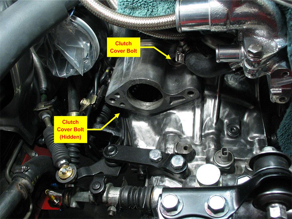
Both are 14mm, one is about 35mm long and the other is about 60mm long. You can see the hole for the shorter one in the photo below, just below the clamp on the bypass hose. The other bolt is hidden, as it's under the left side of the starter housing:
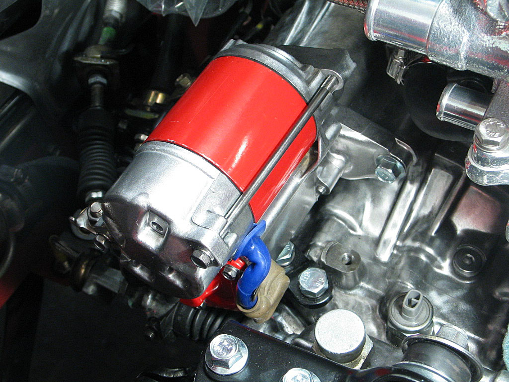
...and two 14mm bolts secure it.
Attach the starter cable (the heavy gauge cable), but don't tighten it down yet, as you'll need to connect the starter relay wire later to this same mounting stud.
I attached the body side back when the engine bay was empty.
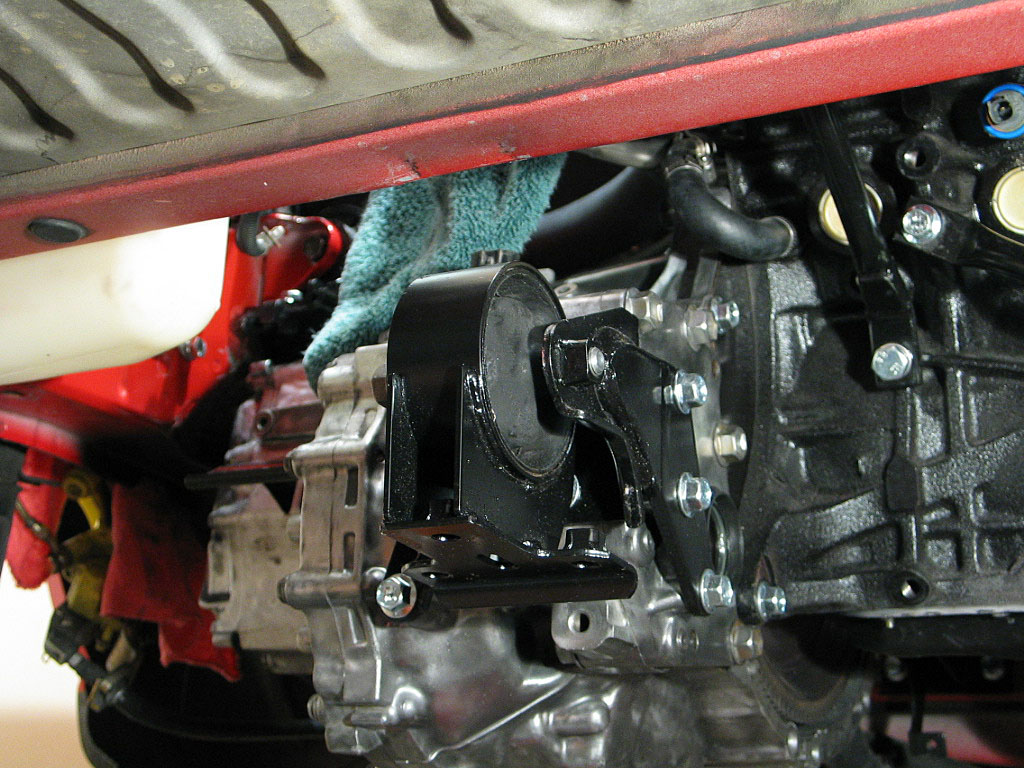
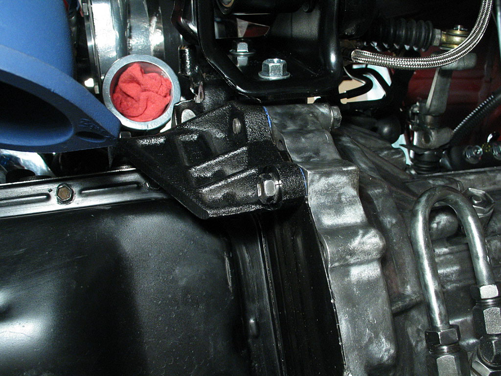
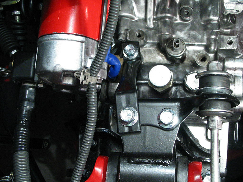
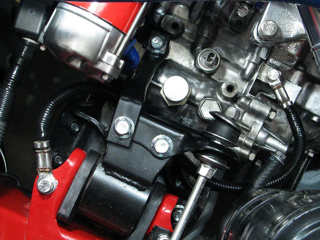
First, attach only the rear 14mm bolt (on the right in the photo above). Just finger tight at this point.
To the left of the control rod is a short engine brace, called the "Engine Mounting Stay". It mounts between the transaxle case and the left motor mount. Install the 14mm bolt through the brace and into the left-hand motor mount. The other end of the brace attaches to the transaxle case. Torque the mounting bolts down to spec, then you can tighten the nut on the end of the control rod.
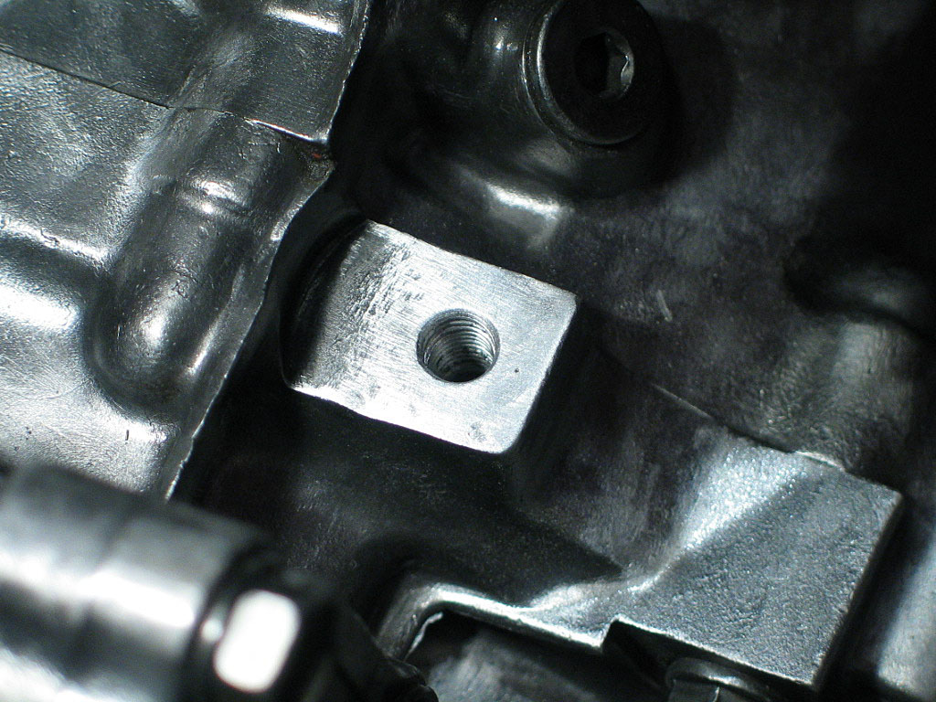
Poor electrical grounds can cause a variety of problems, so I always make an effort to provide solid contact between the cable terminals and the mounting surface. First, I used a spiral wire brush with stainless steel bristles to thoroughly clean the threads where the grounding bolts attach.
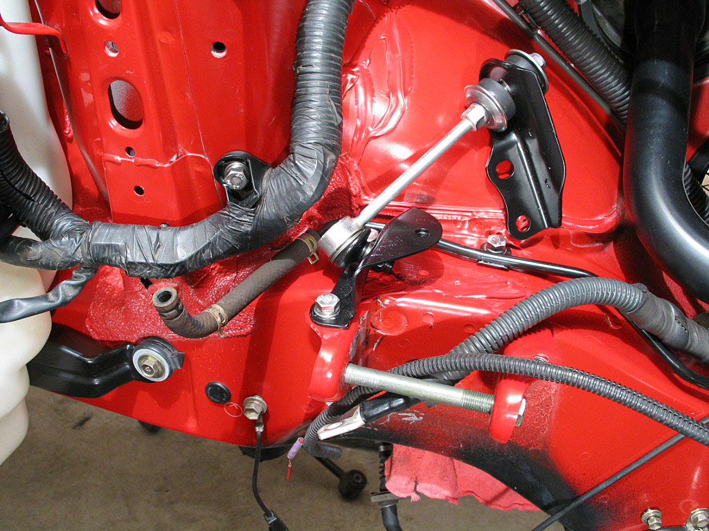
I don't like trusting only the bolt threads to provide electrical connectivity, so I sanded away the finish where the ground cable terminals would be attached, first on the transaxle case...
...and then on the body:
With the contact points prepared, I attached the cable with 12mm bolts:
The intake on the GT30 is big, requiring a 4" ID hose. Most vendors who offer silicone hose elbows only size them up to 3" ID. I found one place that wanted nearly $100 for a single elbow! Fortunately, eBay provided a vendor with more realistic pricing, HighTempSilicone.
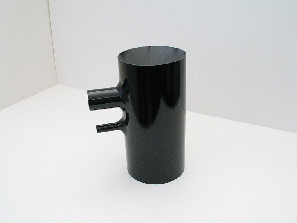
While configuring the piping was essentially a matter of measuring lengths and angles, I also had to provide for some auxiliary air fittings for the BOV, the catch can, and the Idle Air Control (IAC) valve. Since I was working with thin-wall aluminum tubing, and had no welding skills, I decided to chance the small hose nipples to a high-temp epoxy bond.
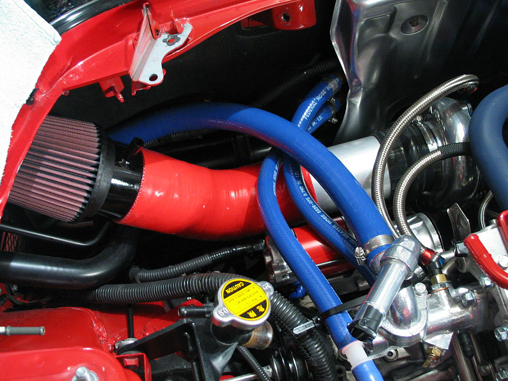
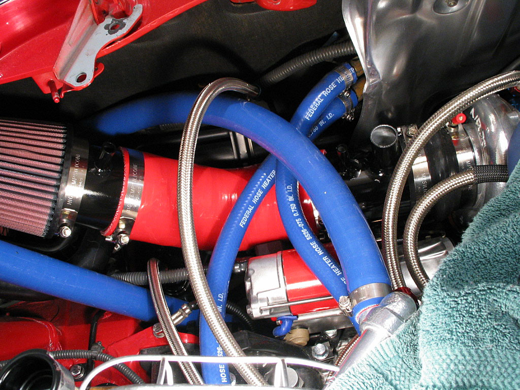
In the photo above, I've already attached a nipple for the ⅝" catch can hose, right near the air filter. I've also replaced the No. 7 coolant hose that runs from the stainless "J" pipe along the firewall to the coolant inlet manifold with a length of 1Ľ" silicone hose. This was done to provide a bit more clearance for the intake pipe. The OEM hose has a "bump" in it that rubbed against the new intake piping.
I used a sanding drum in my cordless drill to round the bottoms of the nipples to match the profile of the 4" intake pipe. When the curvature was about right, I scribed circles the size of the ID of the nipples onto the intake pipe, and drilled the holes to match. A little cleanup was necessary to match the hole sizes perfectly.
I roughened up the surface of the nipples and the intake tube around the holes, to give the epoxy a better grip. I also cut very shallow grooves into the bottoms of the nipples with a hacksaw blade for more bite. I then applied a thin layer of epoxy on the bottom of the nipples and attached them to the intake pipe, making sure they aligned with the holes. Then I waited.
One problem with using epoxy was the waiting time. I needed several layers of adhesive to create a strong bond. The epoxy takes about 15 hours to cure, so it took a full day between each layer. Here's a shot of the tube during the process:
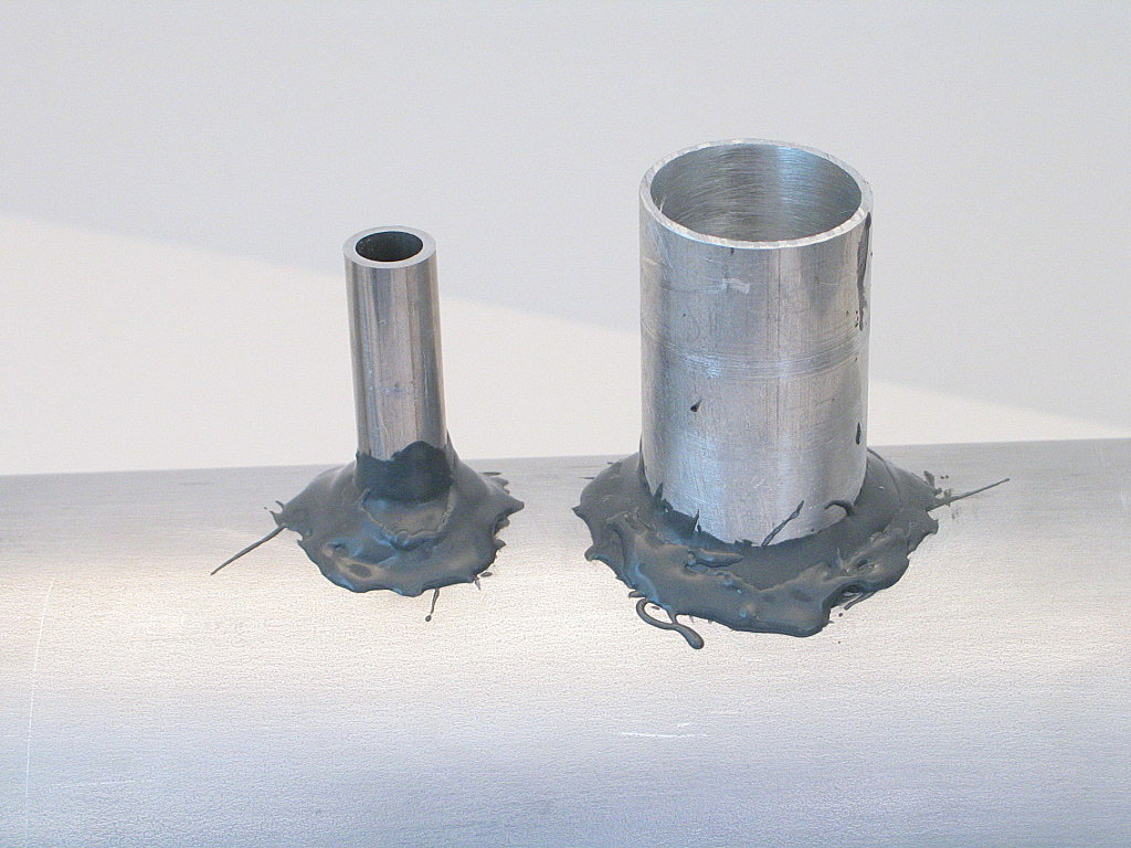
I used three layers on top of the initial thin layer, sanding between each application. It's a lot like working with body putty. Patience is definitely a virtue, but this entire project had already taught me that lesson.
I added a bung for an intake air temperature sensor on the short length of pipe near the intercooler:
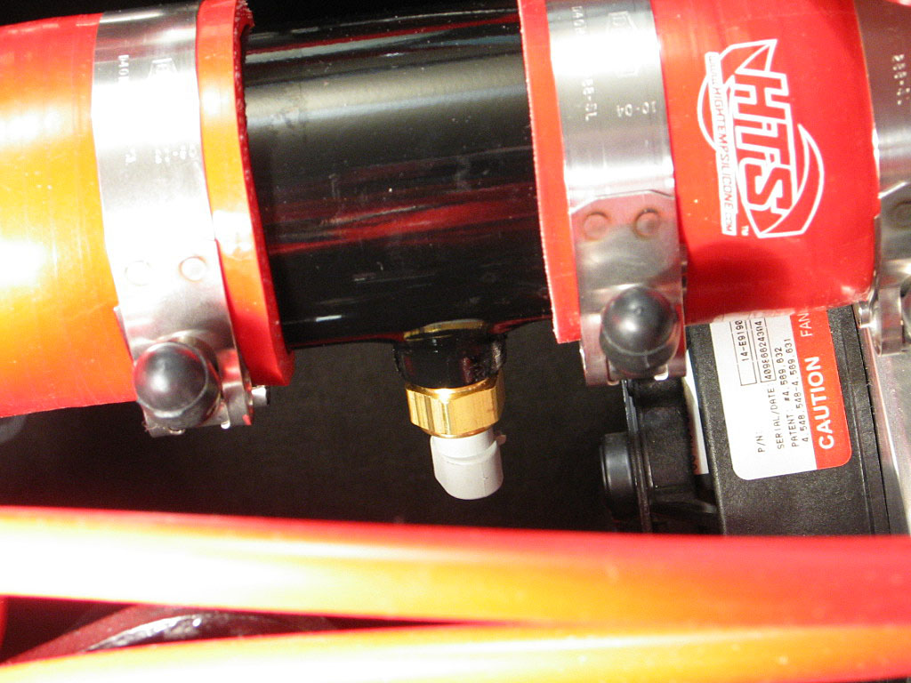
I plan on using this sensor to trigger the intercooler fan.
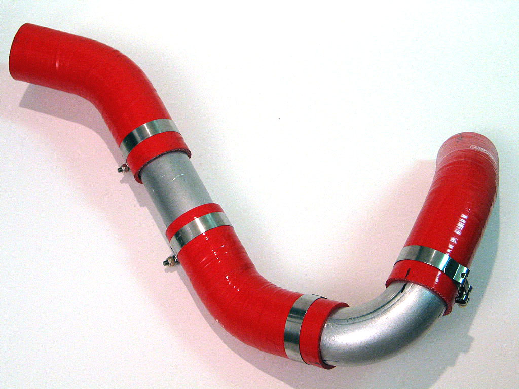
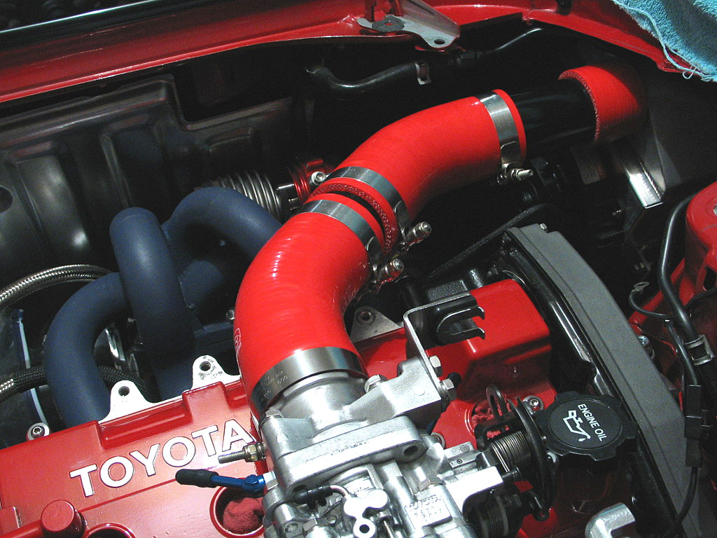
There's a single 90ş bend, with a larger, gentler bend radius than the OEM BOV pipe. There are three large-radius 45ş bends. The Greddy solution, combined with the OEM Toyota BOV pipe, effectively uses three tight 90ş bends, quite a bit of restriction.
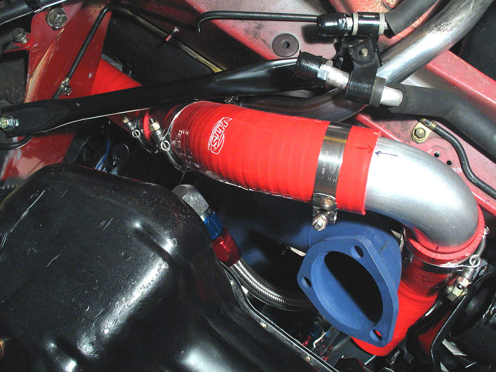
My decision to go between the motor and the forward firewall means the pipe passes close to the downpipe, but the downpipe is ceramic coated to reduce heat loss, and I'll be able to take advantage of the cooling airflow under the car, rather than the hot air on the top. The silicone hose is rated at 500ş F, so it should be up to the task.
Here's a look from under the car during the fabrication and fitting process:
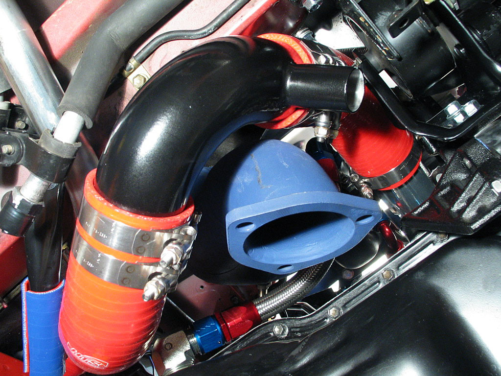
I'm not really sure where to mount the BOV. Up in the pocket near the wheel well is a good spot, but it's pretty far from the compressor.
At this stage, the turbo-to-intercooler plumbing is finished. The compressor housing has been tightened down in the proper orientation and the clamps have been installed.