Last Updated
08 November, 2004
 

  Back to Start                                          Page      1  2  3  4  5  6  7  8    


Rebuilding the 3SGTE (continued)

Transmission and Clutch

     
The transmission from the crashed MR2 had received a few new gears and new synchros not too long ago, so no major changes were planned for this part of the project.

First on the agenda was cleaning the case. There were many years worth of baked on dirt and grease:
Click to enlarge
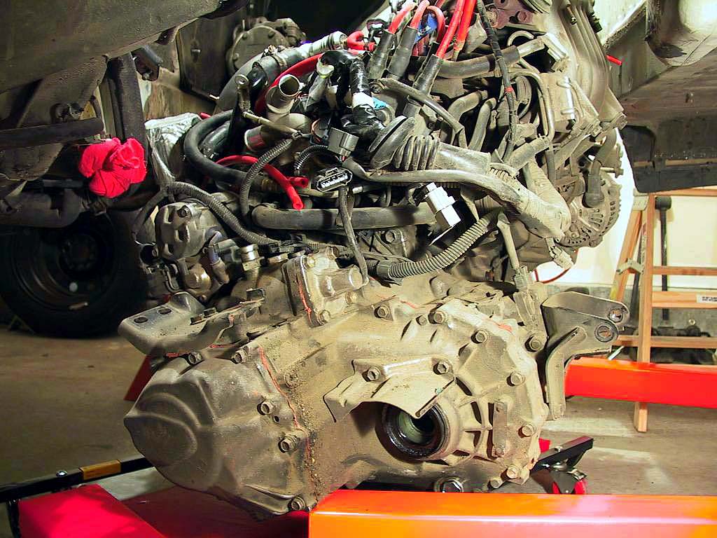
This seemed like the perfect time to clean it up.
 
After much work scrubbing away the dirt on the exterior, and the fine black powder on the inside of the bellhousing, I ended up with a clean but badly discolored aluminum case. I decided to use a small wire wheel to restore, at least partially, the luster of a new case. This turned out to be a very long, time-consuming process.

A Dremel grinder is too small to really do the job. It heats up too quickly, and the small wire brushes shed their bristles in no time. I decided to step up to a Makita die grinder, which used larger (1/4" shaft) bits.

While the Makita would handle a larger area, the end brushes I was using would shed their bristles just as fast as the smaller Dremel brushes. And the bristles would stick to everything, especially clothing. Since they were made of stainless steel, trying to remove them with a magnet was useless. And they weren't cheap, either.

I finally found a solution, in a special end brush with a plastic collar around the bristles, called a Vari-Trim brush (McMaster-Carr Part No. 4911-A18). This collar kept the bristles from splaying out and breaking off. Plus, when the bristles were worn down, half of the the collar could be removed to reveal additional bristle length.

While this didn't entirely solve the problem, at least I could work for an hour or so without covering everything in sight (including myself) with tiny stainless steel wire bristles. Although the Vari-Trim brushes were about twice as expensive as the standard type, they lasted long enough to get some serious work done.

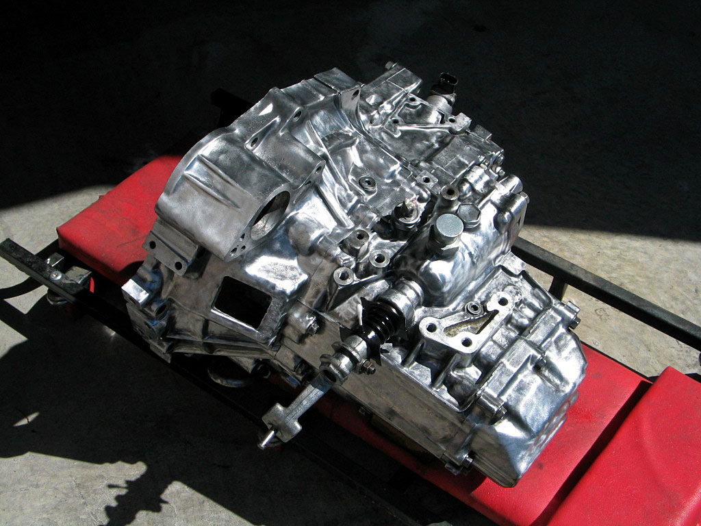
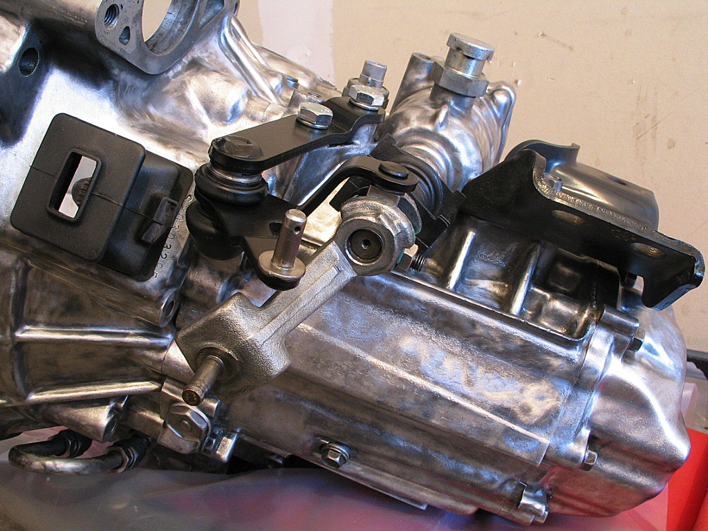
In the end, after many hours with the grinder, the results were OK, although the wire brush produced an uneven satin finish, depending on how the light catches the surface. I applied a few coats of clear engine enamel to (hopefully) keep the surface from oxidizing too quickly. Here's a shot of the finished case:
Click to enlarge
 
Next, I installed the left-hand mounting bracket to the transaxle case, and torqued it down to factory spec:
Click to enlarge
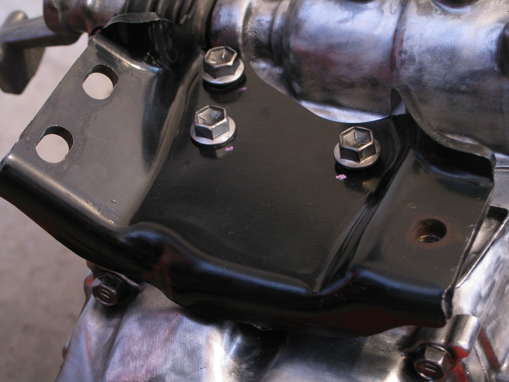
NOTE: This is one of those areas where the published torque specs are questionable. The various M10 mounting bolts used on the transaxle case are threaded into an  aluminum casting, yet the torque specs run from 27 ft. lbs. to 57 ft. lbs. I have to say that 57 ft. lbs into an aluminum thread makes me nervous.
 
The bellcrank, also known as Gear Selecting Lever No. 1,  moves the shift arm in and out of the case. It attaches to a pivot shaft on a support bracket that bolts to the tranny case, and uses uses plastic composite bushings. My bushings crumbled into pieces when I disassembled the components. I special ordered replacements from Toyota, which took about four weeks, then promptly misplaced them. When I tried to re-order, at first I was told they were unavailable. After some checking, the parts man told me they were available, but with 3-4 weeks delivery time. I decided to locate some commercially available bronze bushings to replace them.

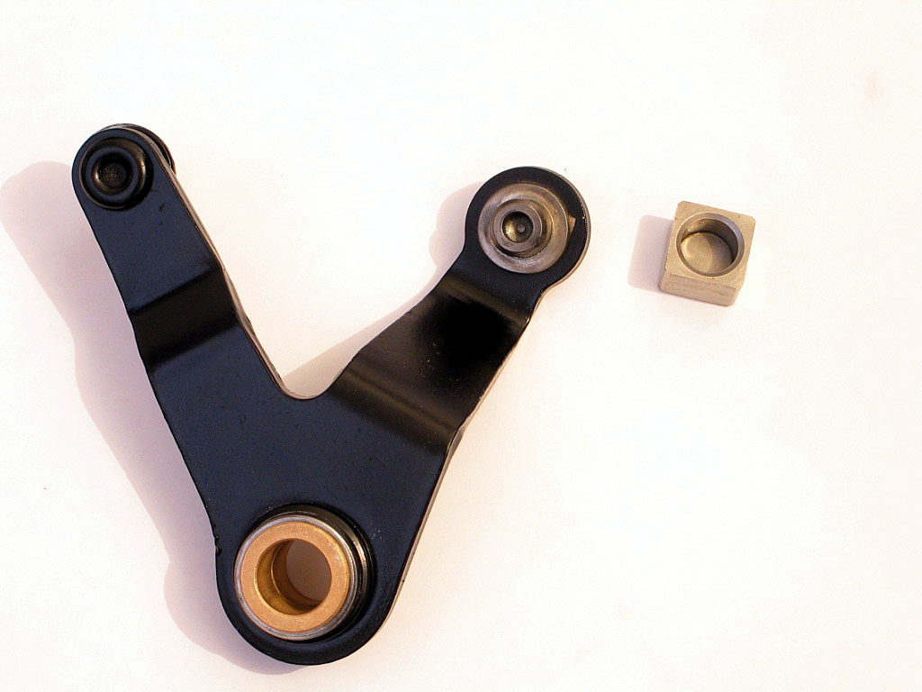
McMaster-Carr sells a bushing that is almost a perfect fit.  It's their metric flanged bushing Part No. 6659K11. The dimensions are 12mm I.D. and 15mm O.D. It's just a bit too long (12mm), so I ground about 1.5 mm off the length of each one for a perfect fit:
Click to enlarge
 
I installed the bellcrank onto its mounting bracket. I then applied some Magnalube-G grease to the shaft that the square follower shoe fits onto, then attached the bellcrank mounting bracket to the transmission. The shoe fits into a groove in the gear selector arm:
Click to enlarge
 
  I replaced the axle seals on both sides of the transfer case...
Click to enlarge
Click to enlarge
...making certain to smash my thumb with a rubber mallet in the process.
 
 
I attached the protective shield that fits above the drive shaft:
Click to enlarge
 
  In addition to the left-hand mounting bracket, the rear mounting bracket can also be attached at this time. It uses six M10 x 1.25 bolts to secure it to the case. Watch your torque specs:
Click to enlarge
 
 
  A new throwout bearing was a part of the rebuild. The new bearing comes with a new retention spring, and attaches easily to the release arm:
Click to enlarge
Click to enlarge
 
 
  I applied some Magnalube to all of the contact points, and installed the assembly into the bellhousing:
Click to enlarge
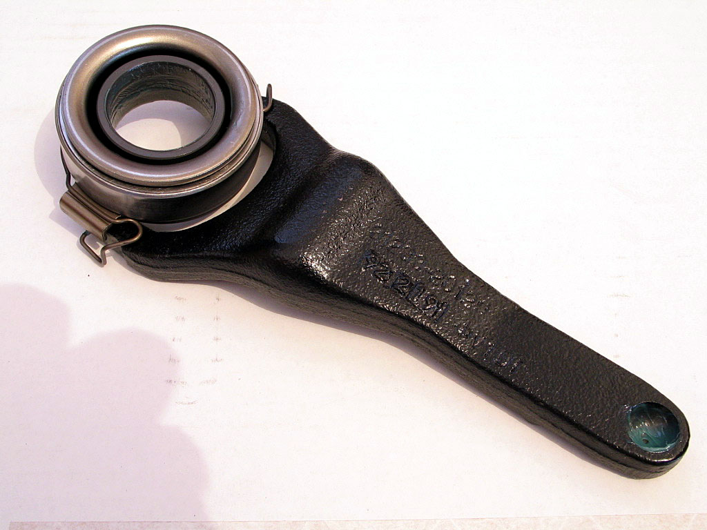
I also applied some Magnalube to the spline.

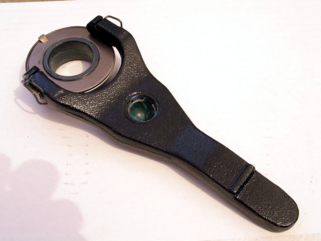
NOTE: Make sure to check the ball that the release arm pivots on for roughness or other damage. It's a cheap and easy replacement now that will pay off later in smoother clutch action.
 
 
That's about the limit of what I could do with the engine in the stand. Once I get the engine on the hoist, I'll be able to assemble the transaxle to the motor, with the new pressure plate and clutch disk.

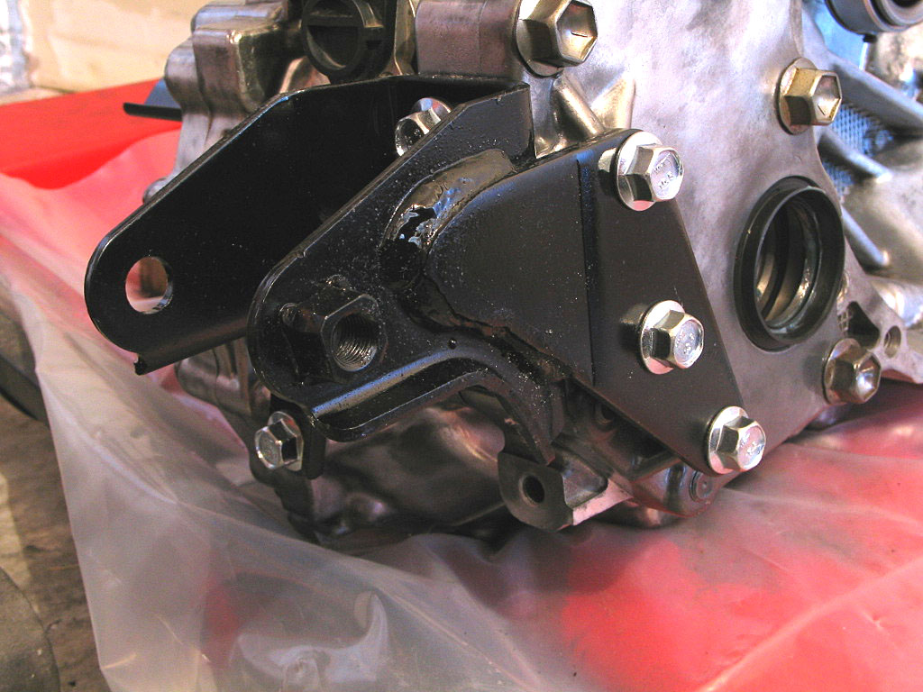
Additionally, I need to transfer some components (like motor mounts) from the "old" motor to the "new" motor.


Jump to installation section...


  Back to Start                                          Page      1  2  3  4  5  6  7  8