26 February, 2005
Rebuilding the 3SGTE (continued)
Mounts and Accessories
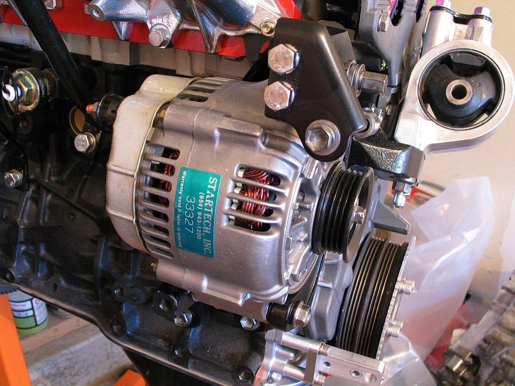
First, I reinstalled the studs that support the alternator bracket:
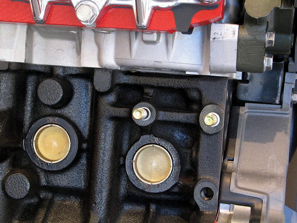
I used a hi-temp thread lock on these studs.
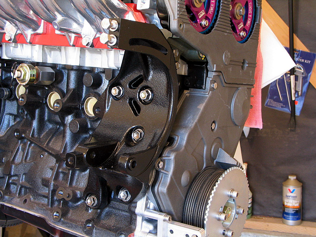
Why in the world Toyota felt it necessary to add 100 extra pounds of bracket (OK, a slight exaggeration) for a single alternator is beyond me.
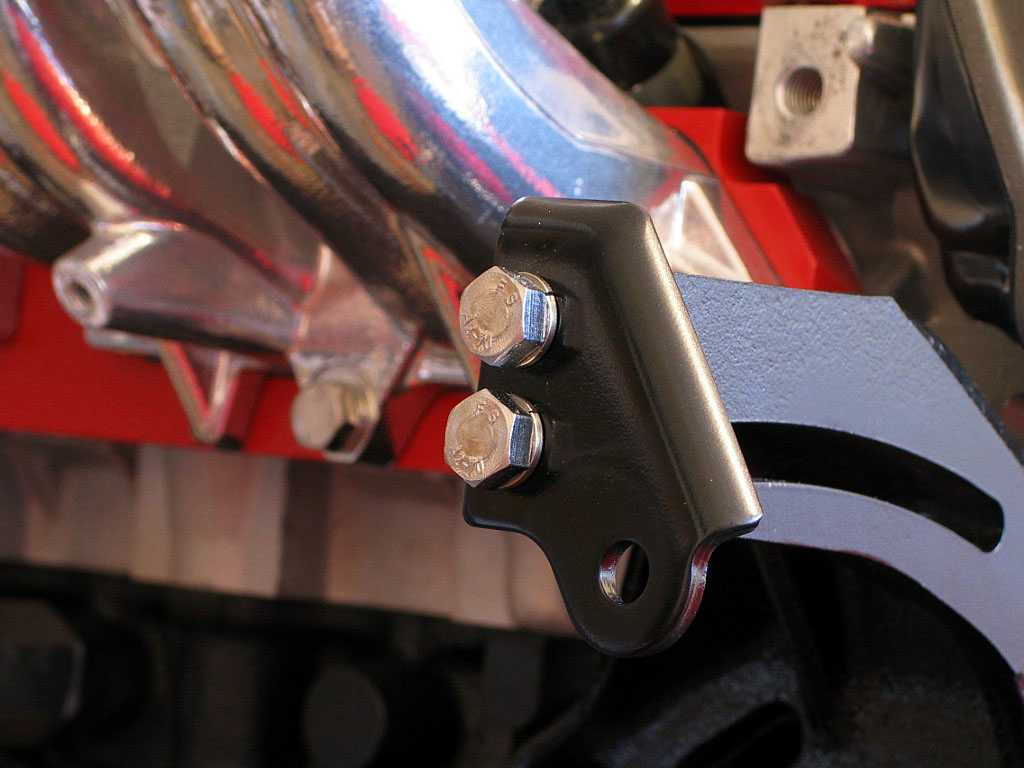

I attached these two arms with some thread lock.
To run full-sequential injectors, the ECU needs to know which stroke is the intake stroke. The crank trigger cannot provide that information. A trigger of some type needs to be provided, and using a notched camshaft wheel with a Hall-effect (digital) or magnetic (analog) sensor is one way to supply that data. I decided to use a Hall-effect sensor, and Troy Truglio recommended the Cherry GS100502.
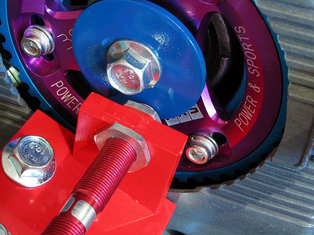
I used a large steel washer (the wheel must be magnetic), with the I.D. slightly undersized for the cam gear bolt. I then drilled it out to about .390", which reduces the potential for an out-of-balance wobble due to off-center placement.
I filed a small (Ľ" x Ľ") notch on the outer edge. Removing this material from one side of the washer would affect the balance. Since the camshaft will spin at upwards of 4000 RPM (8000 RPM engine speed), maintaining a balanced wheel seems worth the effort. I ground away some material on the back side of the washer, opposite the notch, to try to maintain the balance.
This is just hand-tight until all of the parts are ready for final assembly, as the exact position of the notch needs to be determined before the bolt is torqued down.

I misplaced the original bolts, so I replaced them with M10 x 1.25 x 60mm Class 10.9 bolts from AAA Metric Supply. I applied a high-temp thread lock and torqued them down to factory spec.
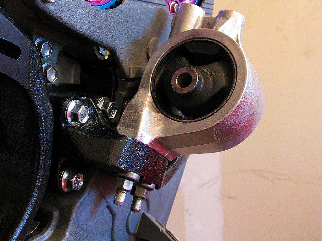
There are two long studs on the bottom of the insulator that secure it to the bracket. These are just finger tight for now.
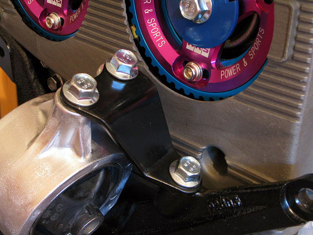
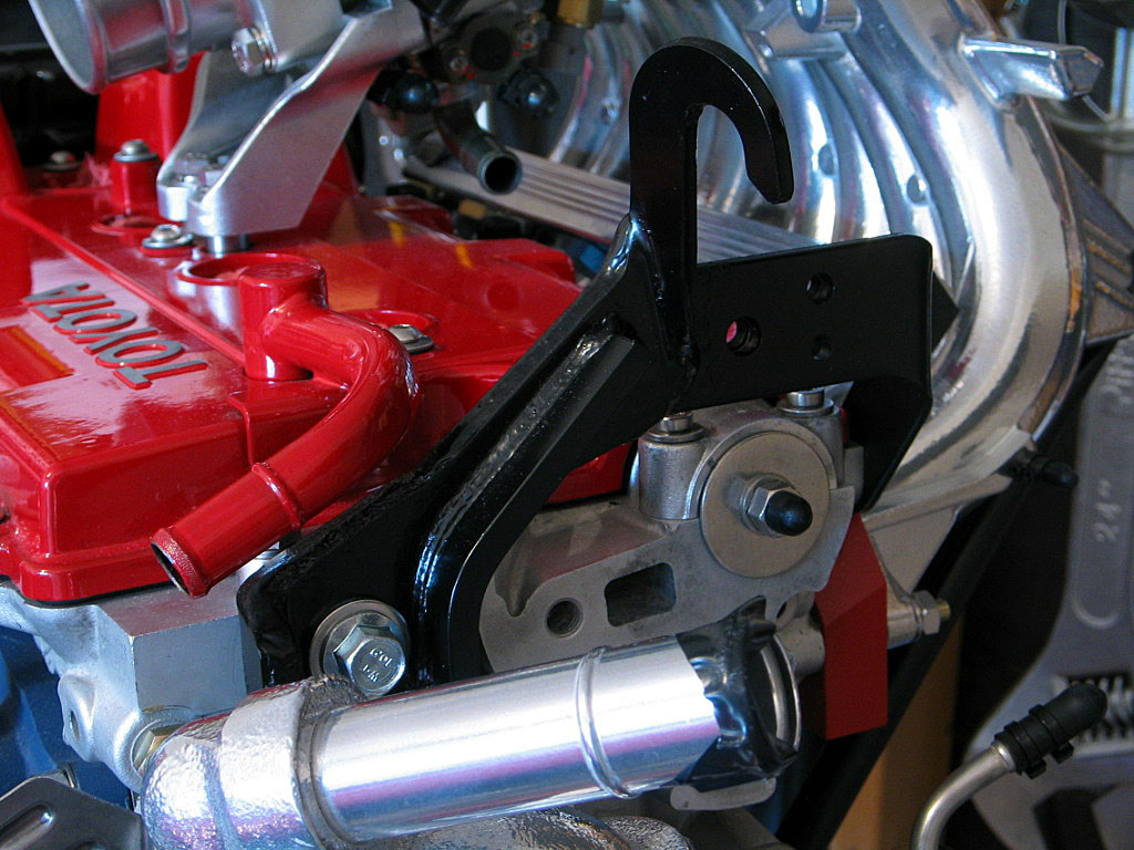
Here I hand-tightened the bolts so I could measure the bolt size and spacing to fabricate the cam sensor bracket.
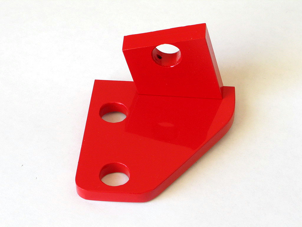
The base is Ľ" aluminum, and the upright is ⅜" aluminum. The upright is secured to the base with two #4-40 x ľ" stainless socket head screws.
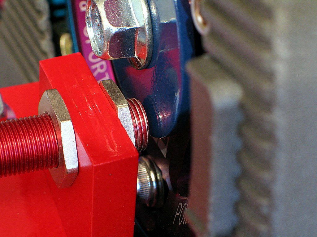
While the sensor itself is a lightweight component, it's vital to secure it rigidly in place, as the clearance between sensor and the spinning trigger wheel is very small. With the trigger wheel spinning so fast, you can imagine the results if the sensor touched the trigger wheel.
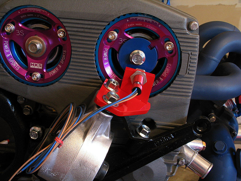
All of the bolts are merely hand tightened at this stage. I just wanted to see how everything fit. I won't install the sensor permanently until the motor has been installed into the engine bay.
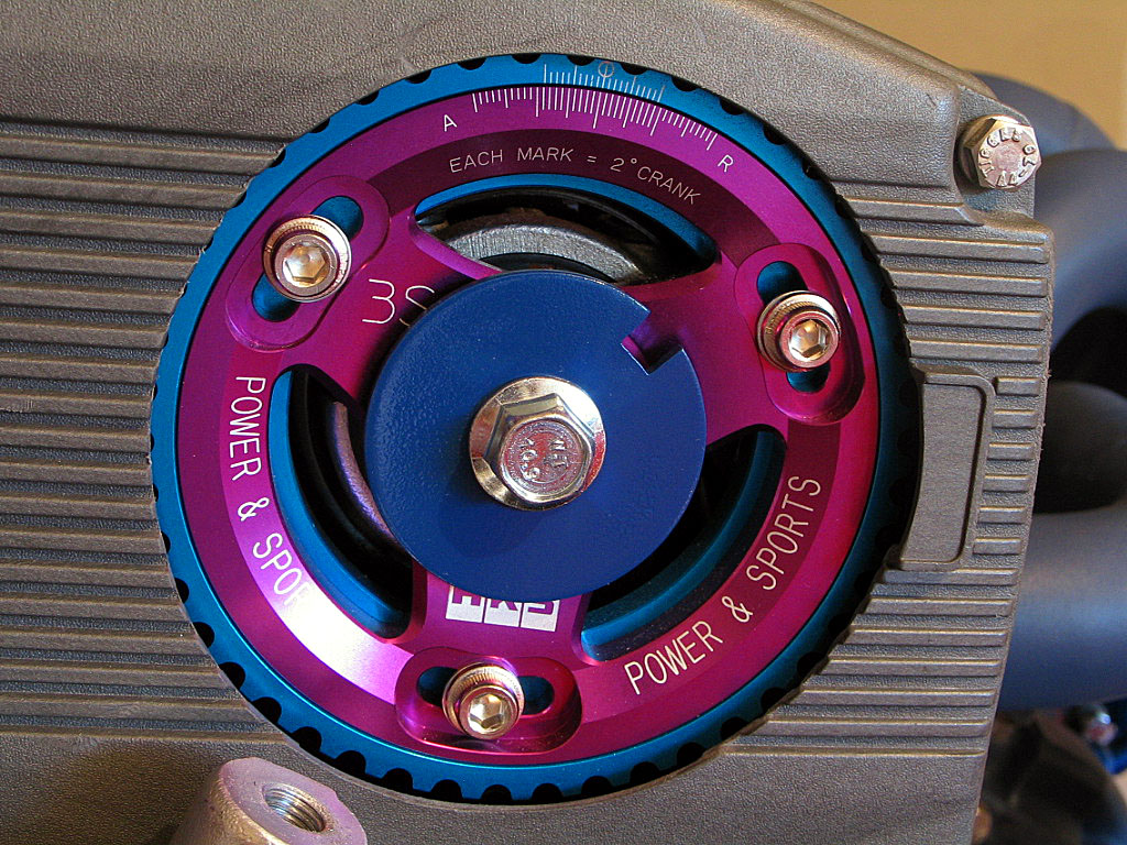
I rotated the crank to approximately 90ş BTDC on the compression stroke and aligned the sensor with the notch in the wheel:
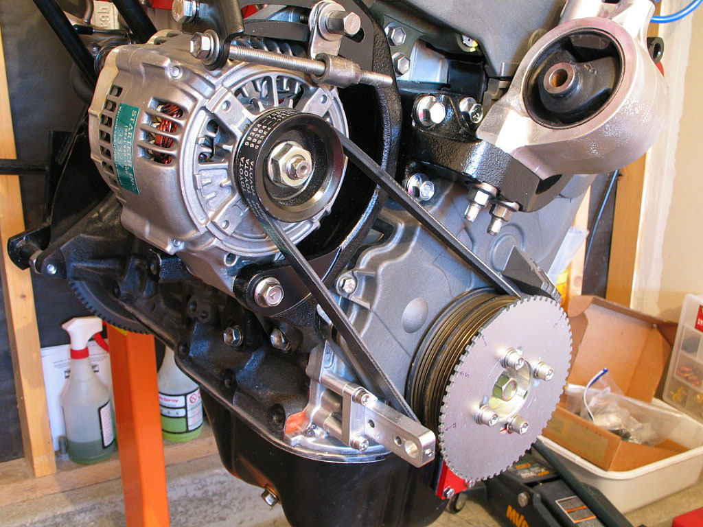
I then torqued down the cam gear bolt and the cam gear timing adjusting bolts.
...and installed the V-belt:
I purchased the basic fittings (˝"-NPT to -8 AN) and plugs, as shown here:
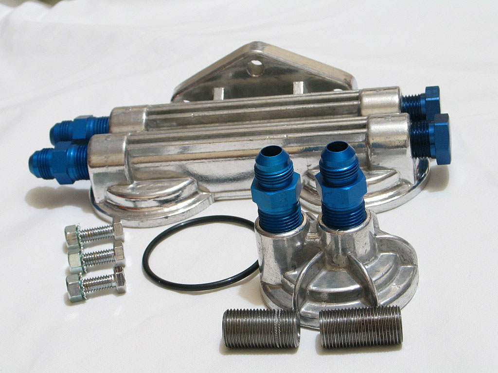
I would use 90ş hose ends on the oil filter adapter, and probably on the oil filter manifold as well.
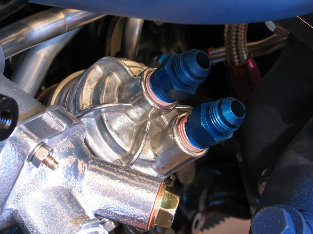
The casting on the adapter was not the smoothest in the world, so I took some time smoothing out the O-ring groove. I then used a little Permatex Ultra Black sealant in the groove to hold the O-ring in place. I then spun the adapter into place on the oil cooler housing, just a bit tighter than you would for an oil filter:
Hopefully there won't be any leakage.
I decided to remove the TD kit, as I could not easily find room for the dual filters, plus I was unhappy with the overall quality of the kit. It would probably work just fine, but I decided to go with a billet adapter and remote filter housing from Canton/Mecca.
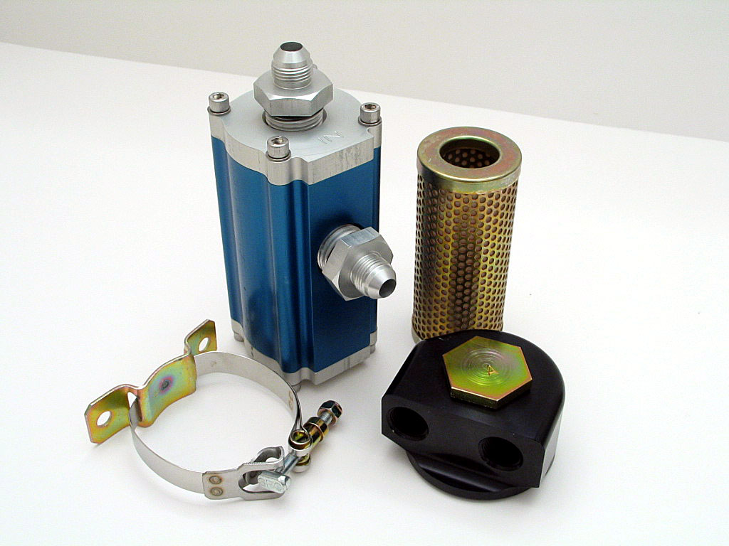
This system was very high quality, and promised to filter out particles as small as 8 microns at a flow rate of over 40 gpm. This high flow rate means a bypass valve in the filter is unnecessary, and the engine oil would always be filtered. In addition, the oil canister was quite small, only 6" tall by 3˝" wide. That made it much easier to mount.
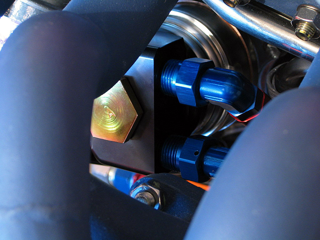
I will be using -8AN 90ş swivel hose ends with ˝" NPT male threads. These need to point down from the adapter to clear all of the various engine components, as space is very tight:
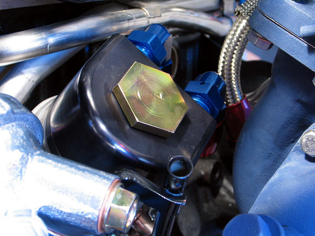
I needed a 1˝" socket to tighten the large bolt that secures the adapter to the oil cooler.
I really couldn't do much more with this assembly until the motor was installed into the engine bay. At that point, I could find a suitable mounting location for the filter, then fabricate the hoses.
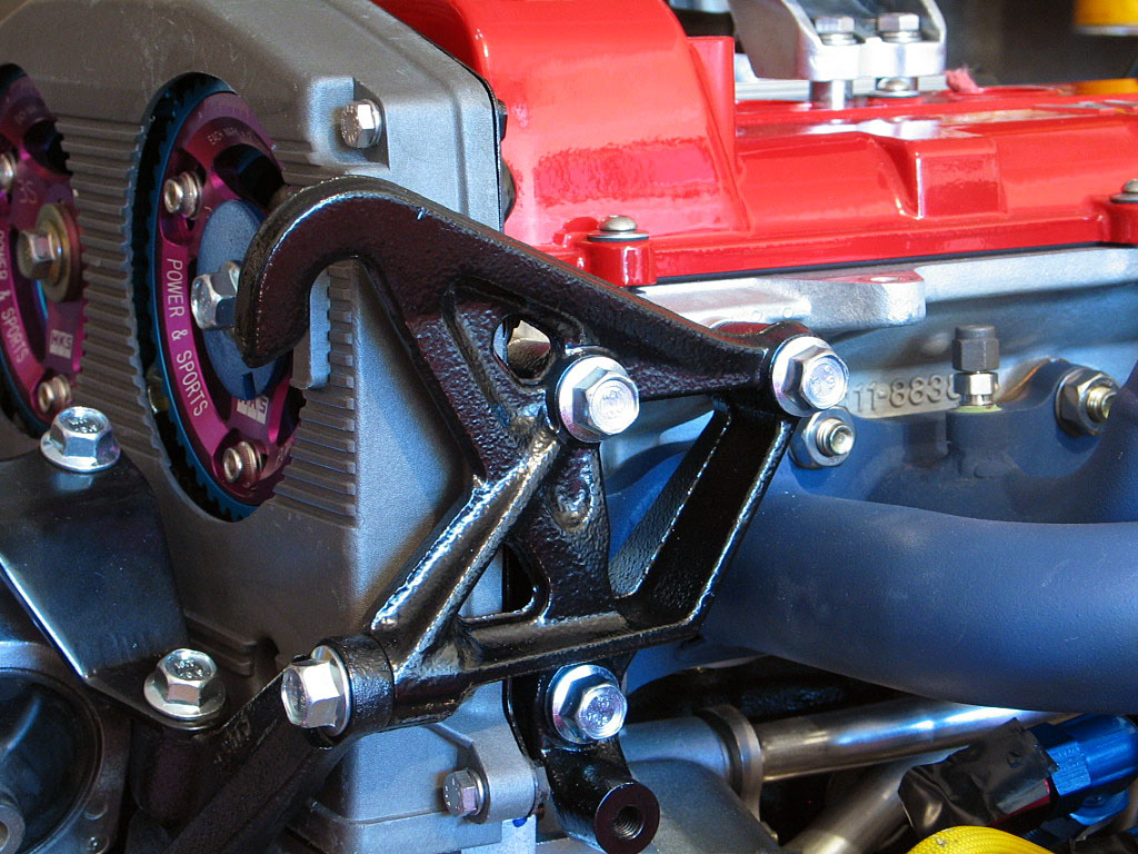
As usual, I used some hi-temp thread lock on the bolts before torquing them down.
I left the bolts just snug, as I might need to remove this bracket while fitting additional components, such as the oil line for the pressure sending unit.
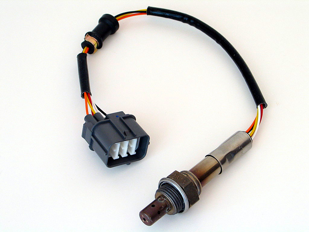
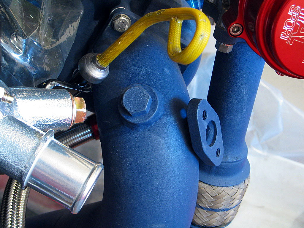
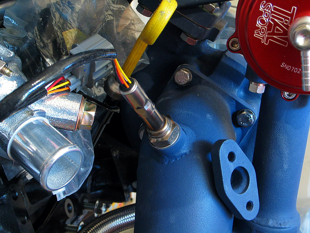
While the stock O˛ sensor's location exposes it to damage during engine removal and installation, the wide-band sensor can be installed prior to assembly.