|
Last Updated
21 February, 2005
|
|
|
Back to Start Page
 1
2 3
4 5
6
7
1
2 3
4 5
6
7
 |
|
|
Rebuilding the 3SGTE (continued)
Sensors |
|
| |
|
|
| |
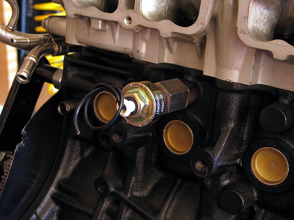
Let's take a look at the other side of the engine.
I need to install the knock sensor.
I'm using a GM-type sensor, with an adapter for the MR2's 1/4" - BSP
(British Standard Pipe) hole. I bought the assembly from Aaron Bunch at
ATS Racing a long time ago, but
never got around to installing it:
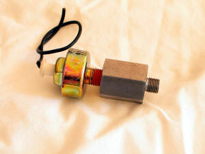
The GM sensor is less expensive and supposedly more rugged than the Toyota
OEM part.
|
|
| |
I used some medium strength thread lock on the adapter, and tightened it
down into the block:

|
|
| |
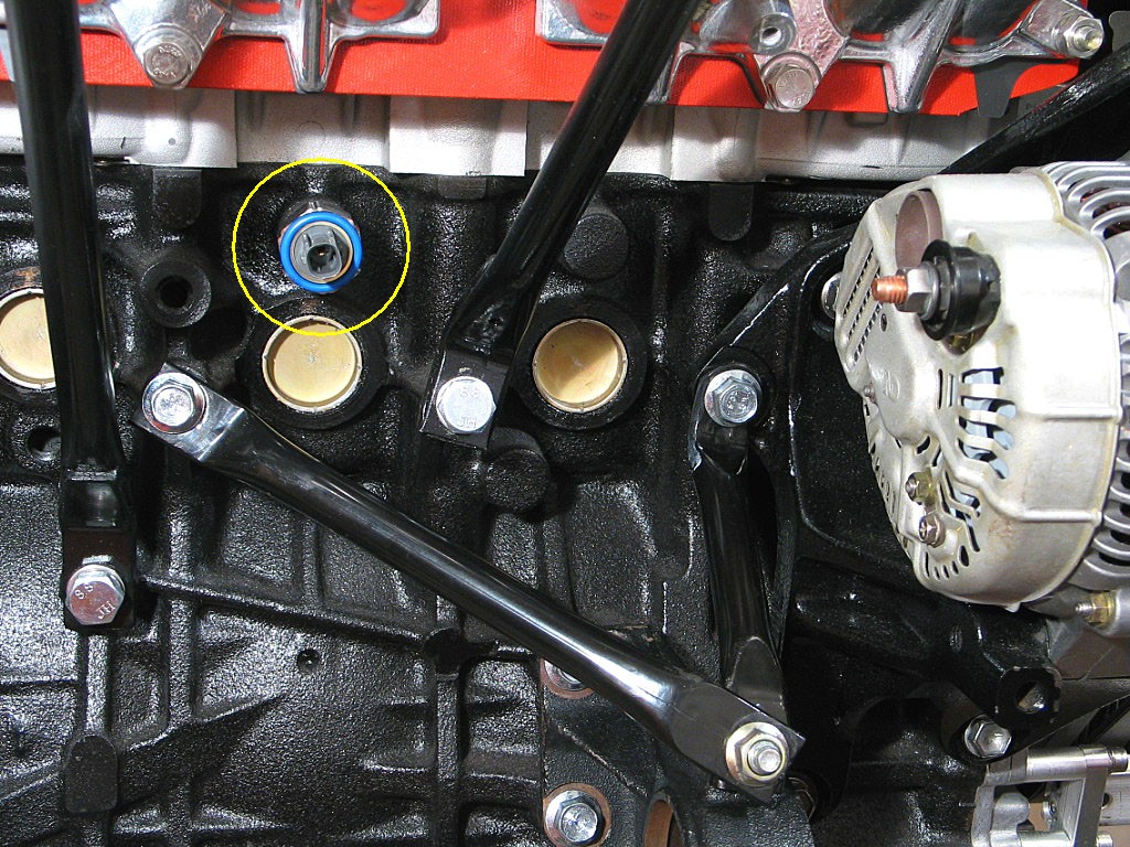
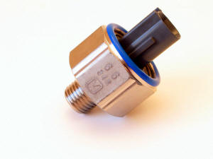
UPDATE:
After reading a
lengthy message board discussion on the characteristics of the GM
knock sensor, I've decided to replace the GM sensor with the OEM unit:
|
|
| |
I removed the GM knock sensor, and replaced it with the OEM unit, using
some thread lock:
|
|
| |
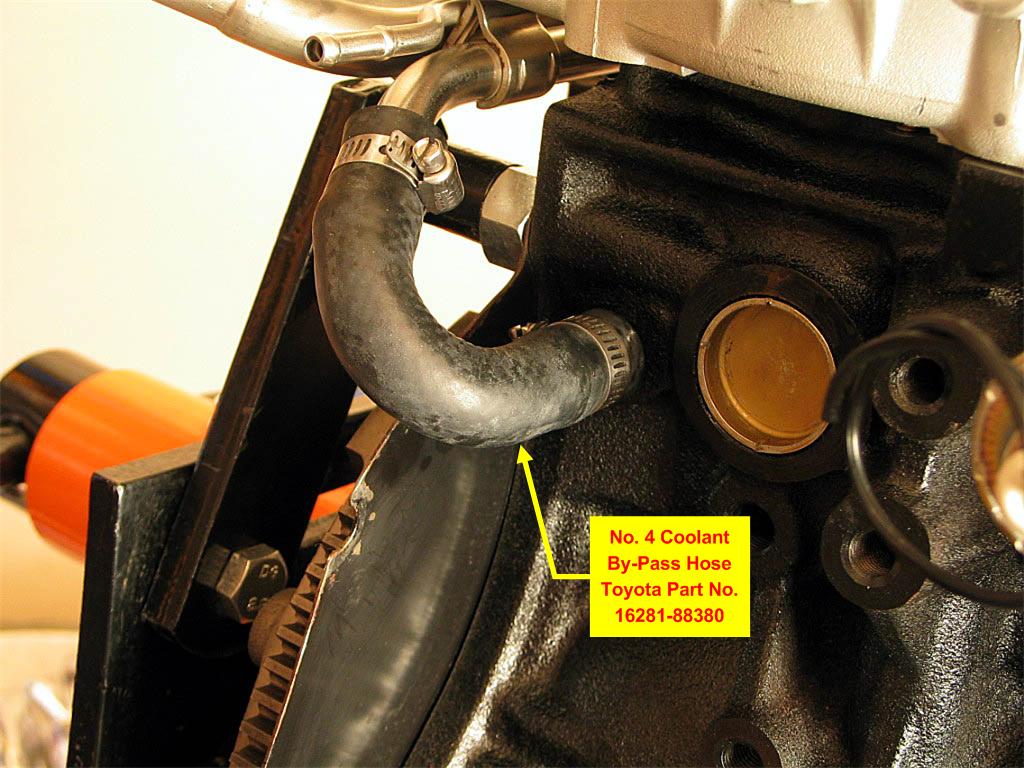
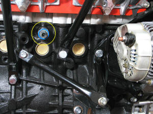
In the upper left corner of the previous photo, you can see the other
end of the bypass pipe that leads to the Hose From Hell. It connects to
the coolant pipe extending from the block just slightly below it with the
No. 4 bypass hose:
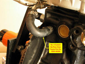
Soapy water is quite helpful in sliding the hoses in place. Again, just tight enough on
the clamps.
|
|
| |
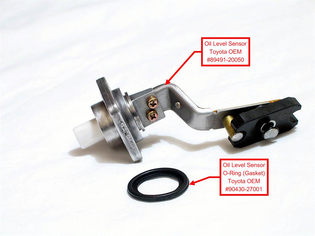
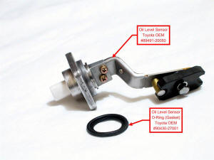
The oil level sensor is located on the front of the oil pan. I'd spent
some time removing the old sealant that coated the sensor. Probably a
fruitless effort, as every sensor I've seen seems to have gasket sealant
liberally applied to stop oil leaks. The Toyota design relies upon an
o-ring to seal the hole:
|
|
| |
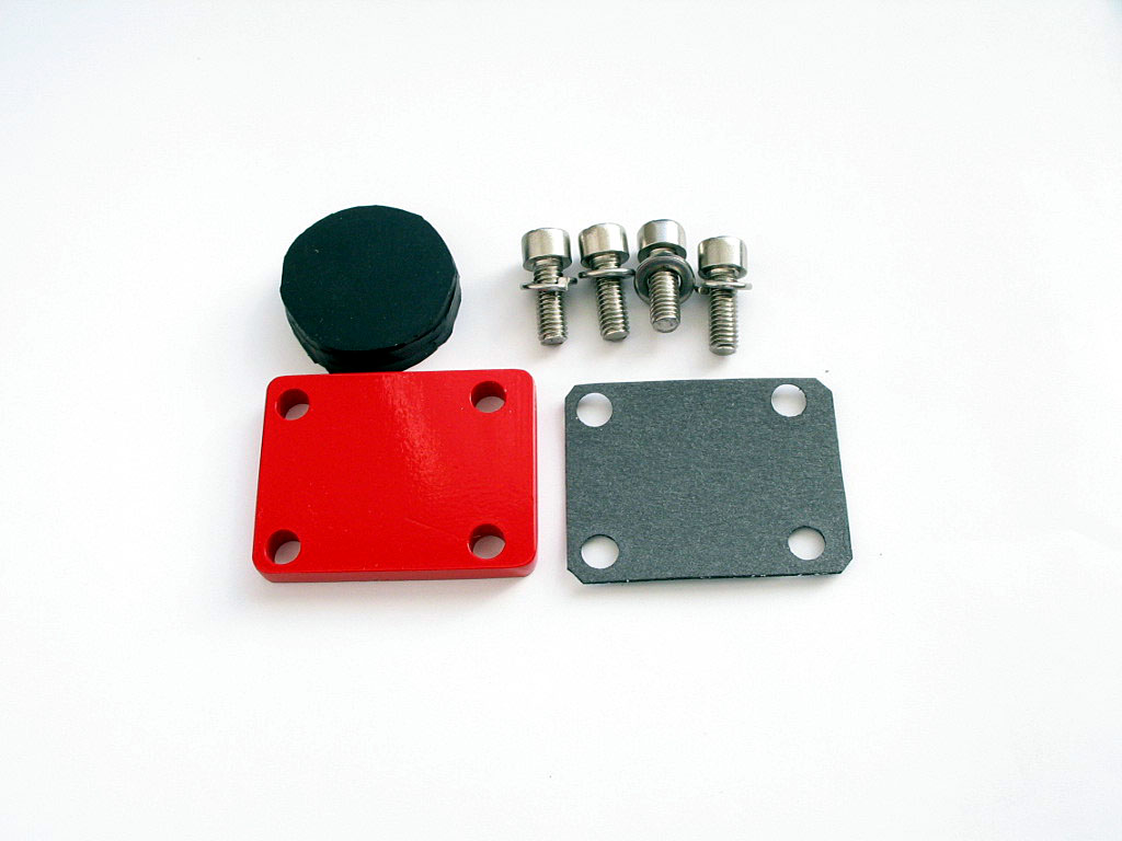
In the end, I decided to simply block off the sensor hole. I've never
really seen the need for the indicator, and the one on my current MR2 is
always coming on even though the oil level is correct.
I fabricated an aluminum blockoff plate, a gasket, and a neoprene plug that I hoped
would prevent oil seepage:

|
|
| |
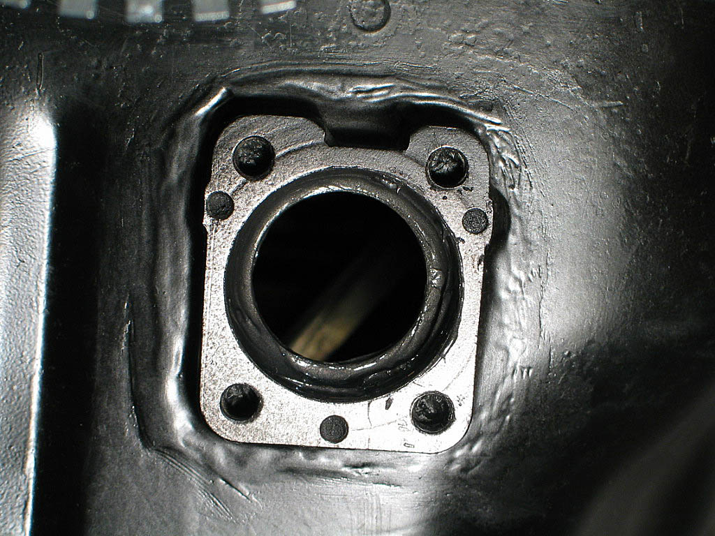
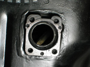
Here's the sensor hole in the oil pan:
|
|
| |
I inserted the plug, which was about 1.25" in diameter, and .375" thick.
That's a bit thicker than the relief in the sensor boss, but that meant
there would be a tight seal around the plug when the plate was tightened
down:
|
|
| |
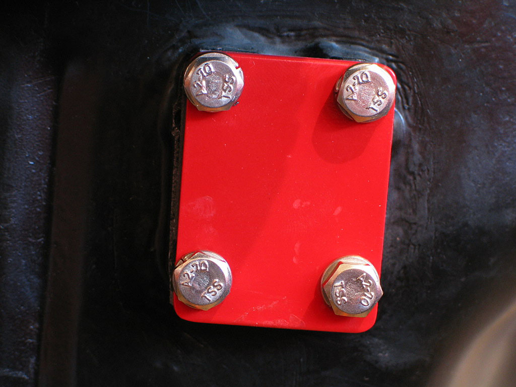
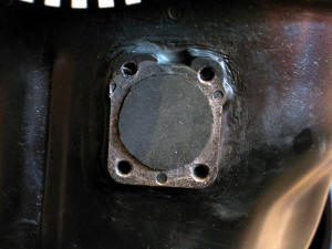
I installed the blockoff plate and gasket, and torqued down the bolts, adding a little thread lock:

|
|
| |
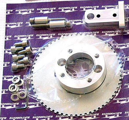
Now I moved on to the TEC� crank trigger wheel.
The TEC� uses a direct ignition, and the system is triggered by a sensor
that reads a toothed wheel mounted on the front of the crankshaft. I was
lucky in that the wheel and the sensor bracket for the 3S-GTE can now be purchased as
bolt-on parts from Electromotive.
Here's a photo of the parts included with the MR2 trigger wheel kit:
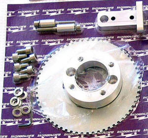
I purchased my TEC� components from Troy Truglio (www.truleo.com).
|
|
| |
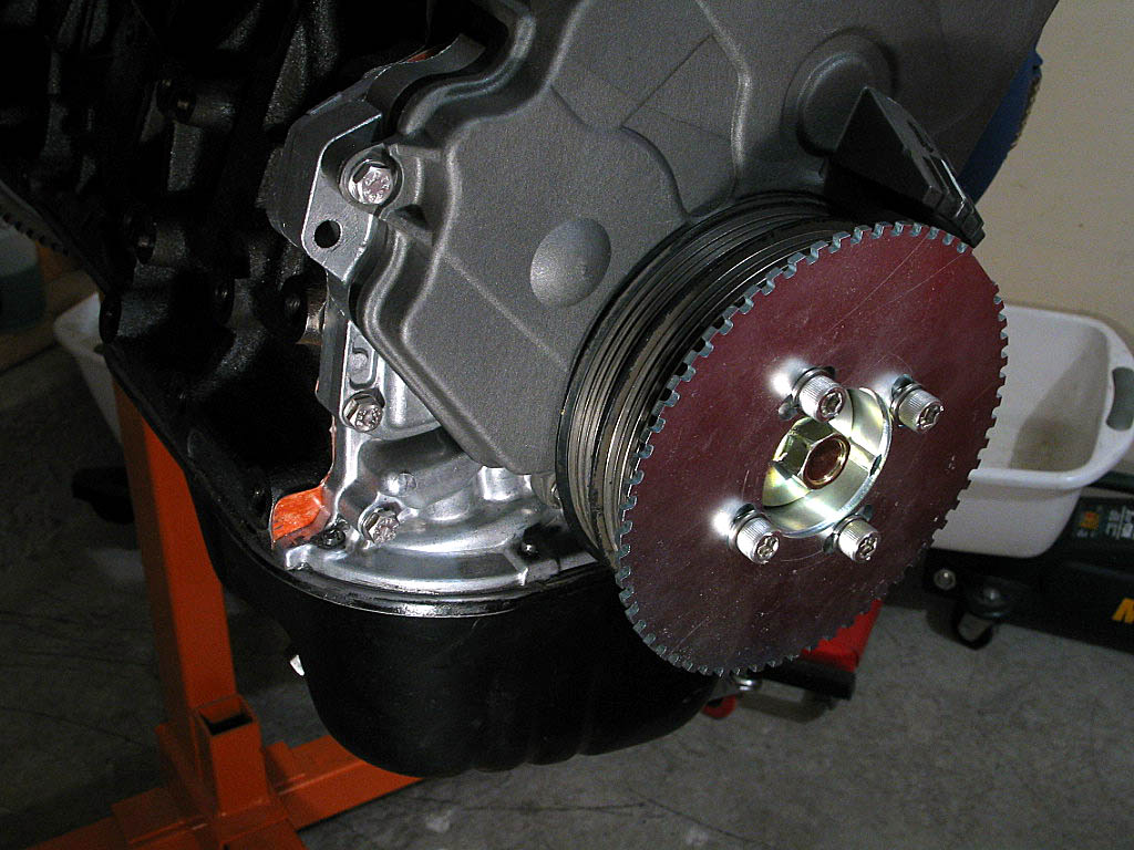
Install the crankshaft pulley (harmonic dampener) and torque it down to
BGB specs.
|
|
| |
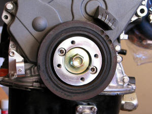
The crank trigger wheel uses a machined aluminum collar that mounts
directly to the crank pulley, using the existing two holes where you mount
a wheel puller for removal.
Mount the trigger wheel collar to the pulley securely. The collar is
designed to center itself around the pulley hub to avoid balance problems.
|
|
| |
Once the collar has been mounted, the trigger wheel is bolted on to it:

|
|
| |
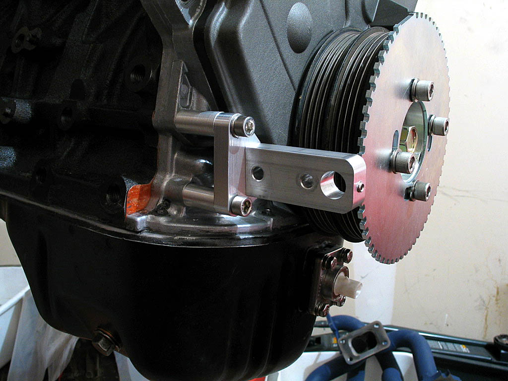
The sensor bracket is then attached to two oil pump mounting bosses:

|
|
| |
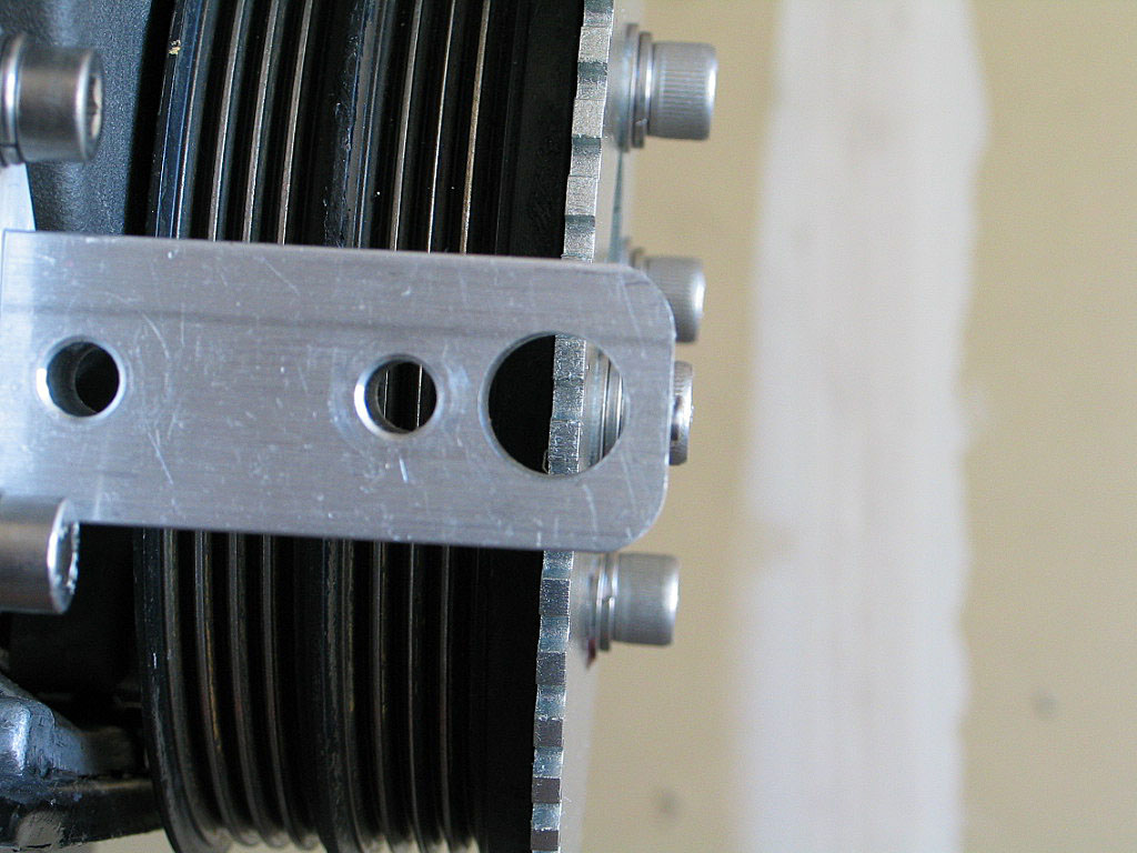
At this point, I'm just checking the alignment of the sensor bracket and
the trigger wheel: y

Final alignment will be performed once the trigger wheel is properly oriented
on the pulley and has been tightened to spec. More on this process in the
TEC� installation section.
|
|
| |
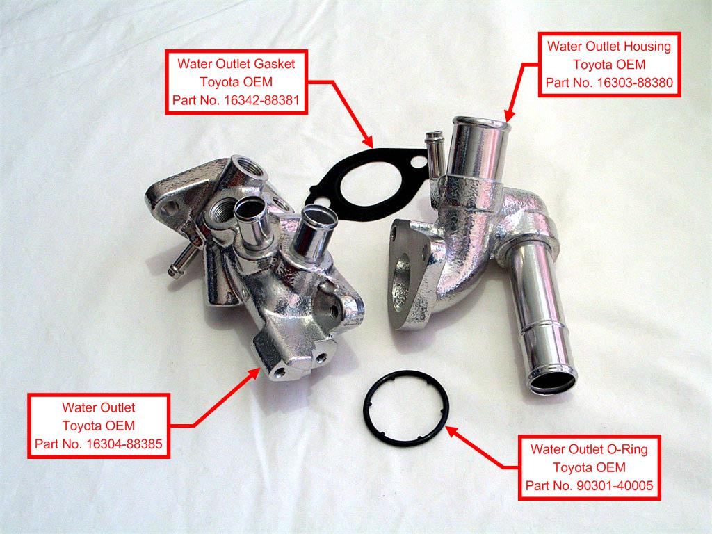
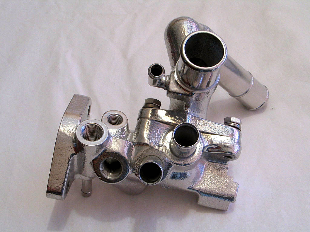
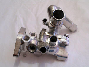
On the back (left) of the motor is a coolant outlet. A
sub-assembly of two coolant manifolds attaches to this, and provides a home for numerous coolant
temperature sensors. Here's a photo of the two main coolant manifolds, which
Toyota refers to as simply "Water Outlet, Part No. 16304-88385" and
"Water Outlet Housing, Part No. 16303-88380":

Here's a photo of the sub-assembly:
|
|
| |
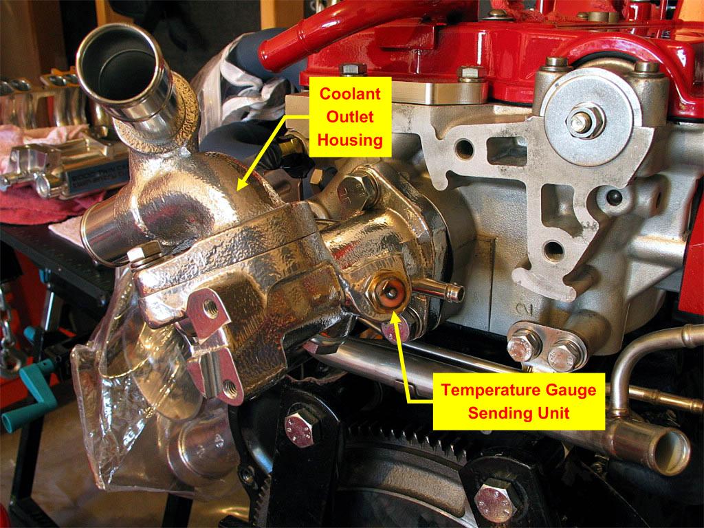
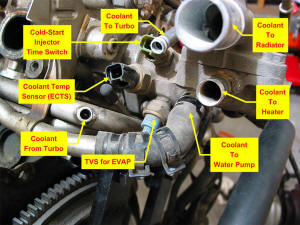
Here's a photo taken during disassembly of the motor:
|
|
| |
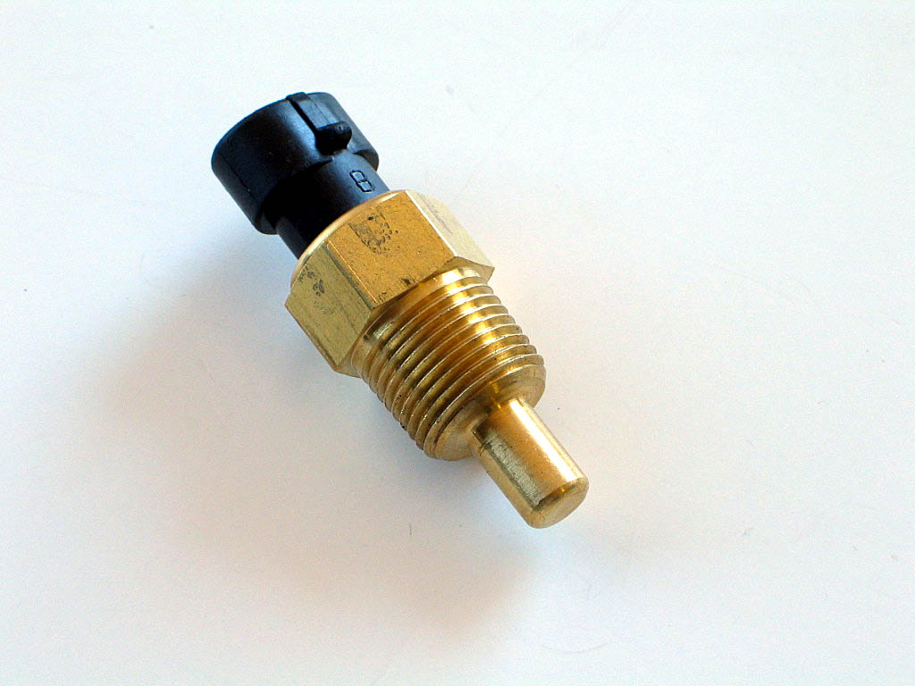
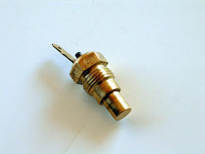
The only OEM sensor I need is the sending unit for the coolant temperature
gauge. This mounts on the opposite side of the housing, so you can't see it in
the previous photo:
|
|
| |
I'm replacing the stock ECTS sensor with a coolant temperature sensor from
Electromotive that's compatible with the TEC�:

|
|
| |
The Electromotive sensor uses a 3/8" - NPT thread. Of course, it would be too easy if this
could simply be screwed into one of the existing bosses. All of the sensor bosses are threaded with different size metric
threads, except for the TVS for EVAP sensor, which uses (you guessed it)
BSP. In this case, 3/8" - BSP.
I
decided to simply tap the ECTS boss to take a 3/8" - NPT thread. That boss
is an M16 - 1.5 thread, which meant I could simply run a tap down through
the existing hole with no additional drilling necessary. While I generally
didn't want to modify the OEM parts I was using, like re-tapping the
cylinder head or block, this housing is
relatively inexpensive to replace (about $40), so I didn't really care.
|
|
| |
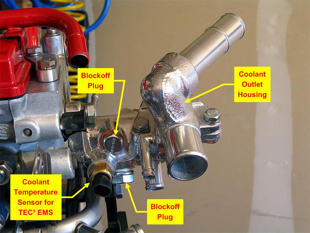
Here are photos of the housing assembled onto the motor:


|
|
| |
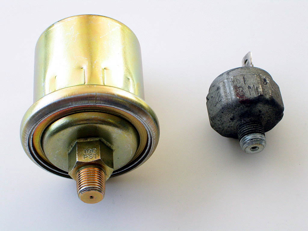
I was planning on installing an Auto Meter oil pressure gauge, and that
required replacing the stock oil pressure switch with the Auto Meter
sending unit. Like everything else, this gets complicated quickly. Here's a photo of
the two oil pressure senders side-by-side:
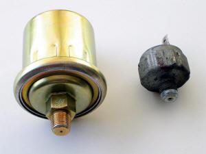
First, the Auto Meter sender on the left is physically much larger and
heavier than the stock switch. Second, here's another example of Toyota's
love affair with British Standard Pipe threads. The OEM unit is 1/8" BSPT,
while the Auto Meter unit is 1/8" - NPT. While the threads-per-inch is
very close (28 TPI on the BSPT vs. 27 TPI on the NPT), the BSPT diameter
is smaller than the NPT spec. So an adapter is needed.
The physical size of the Auto Meter sender means it will not fit in the
stock location, as the coolant housing is in the way. It requires a hose
to be run from the adapter to the sender unit, which would be mounted in a
remote location.
|
|
| |
Finding the correct adapter (1/8" BSPT male - to - 1/8" NPT female) was
more difficult than I had expected. Someone on the message board
recommended a kit from Sunpro which
sells for under $6.00 at AutoZone. It's Sunpro's Metric Adapter Kit
#CP7573.
The correct adapter is included in this kit.
When shopping for BSP adapters, I found that you need to verify that the
thread on the adapter is tapered (BSPT). I found most adapters from U.K.
sources to be parallel threads (BSPP), and the fittings on the 3S-GTE seem to all be
tapered threads (BSPT).
I applied some Teflon sealing compound on the threads and installed the adapter:
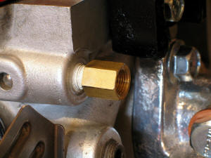
Installation of the hose and sending unit will come later.
|
|
| |
Continued on next page... |
|
|
|
|
|
Back to Start Page
1
2 3
4 5
6
7
|
|
|
|
|
|
|
|
|
|
|