12 November, 2004
Removing the 3SGTE (continued)
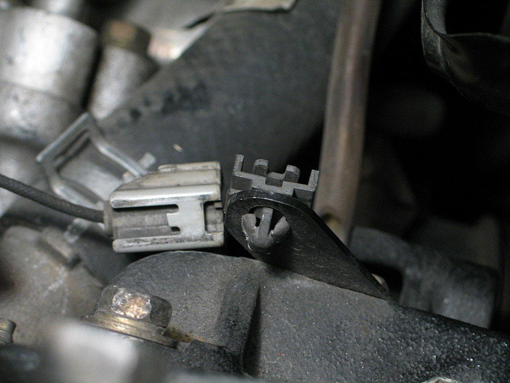
The locking tab must be pried up and away from the housing, then the connector can be separated.
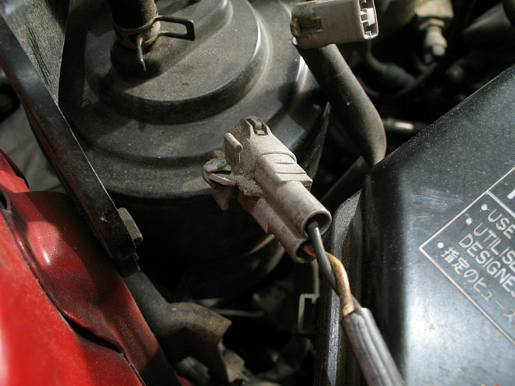
Press the locking tab in, against the housing, then pull to separate the connector.
Don't you sometimes wonder why Toyota chose to use a different connector design for virtually every connector in the engine compartment?
Slide the lower half of the connector out of the mounting plate, as the other end is attached to the A/C compressor:
I recommend cutting a piece of pressboard and placing it in front of the intercooler to avoid damage to both the cooling fins and your knuckles.
You can just barely fit a 14mm offset box wrench onto the nut. Carefully loosen the nut just enough so it turns easily.
Loosen the bolt until the drive belt is completely slack.

There's more fun ahead!
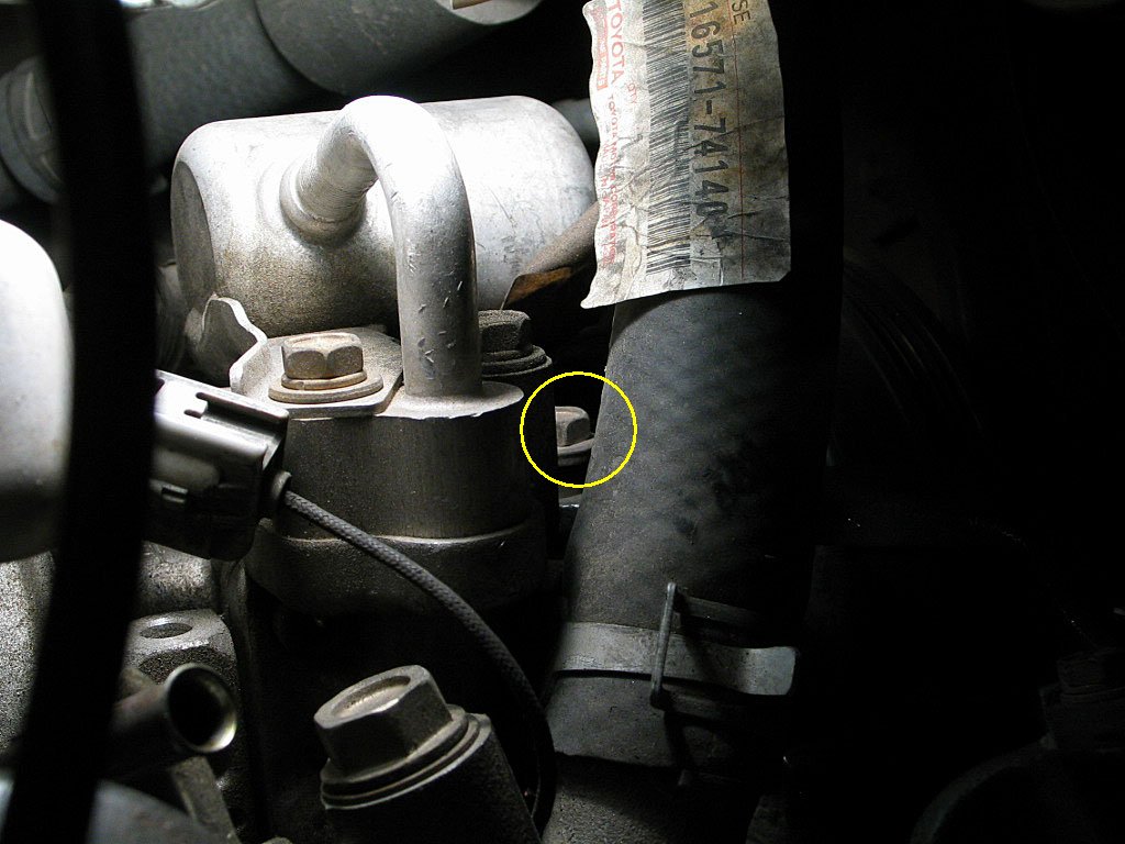
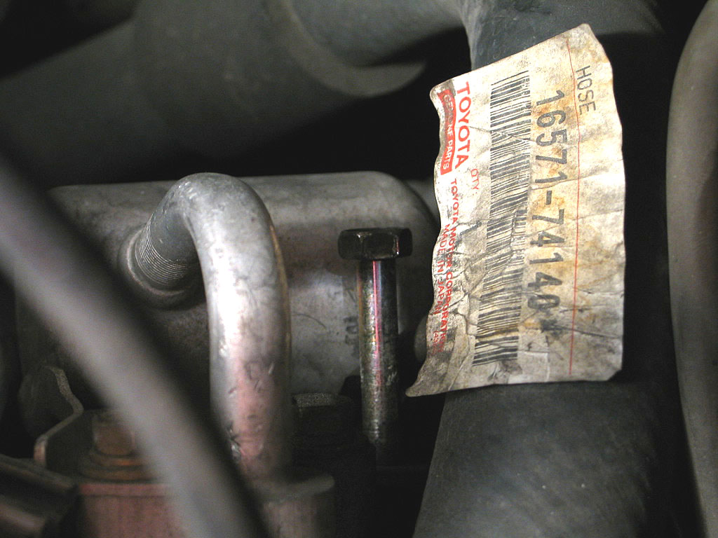
While it might be easier to reach this bolt with the coolant hose removed, it's probably better to do it now with the vehicle at ground level. A 12mm socket on a short extension will do the job:
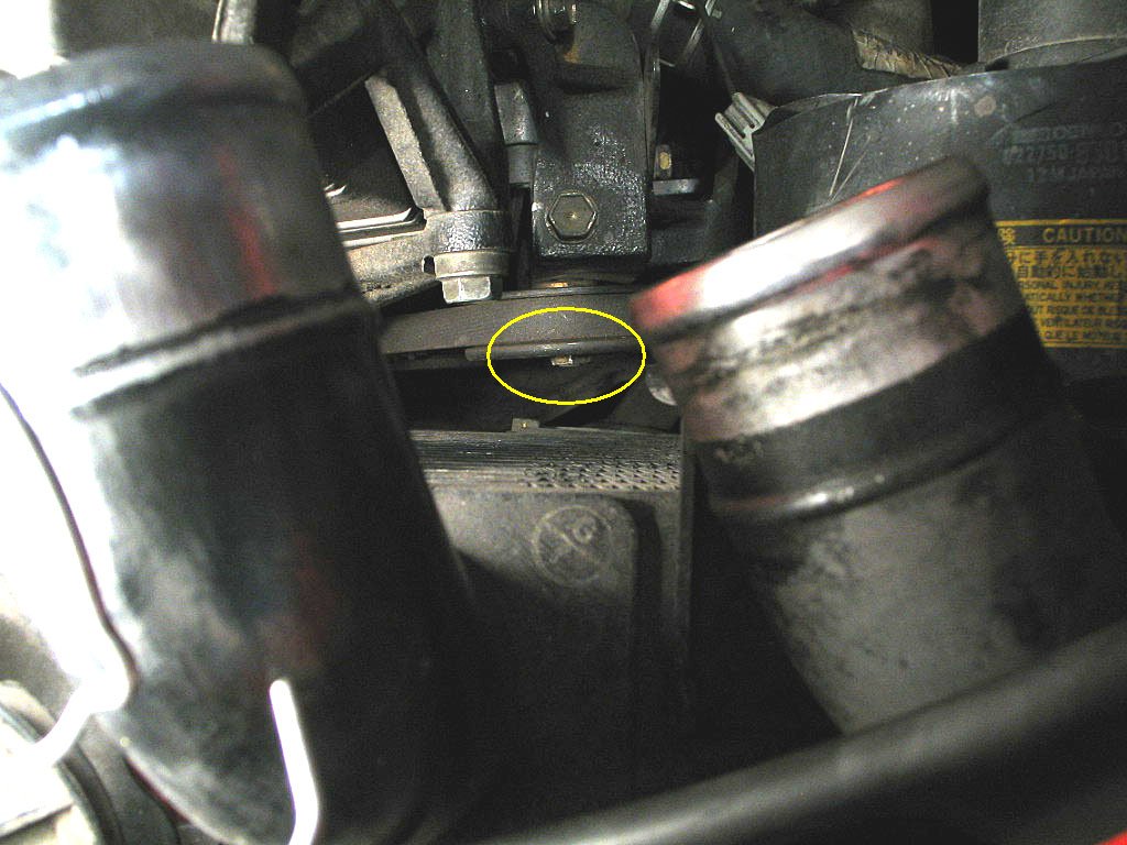
While the upper A/C compressor mounting bolt was removed in the previous step, there's another problem. One leg of the idler pulley bracket fits in front of the upper A/C compressor mounting boss. Here's a photo from later in the removal process that shows the blockage:
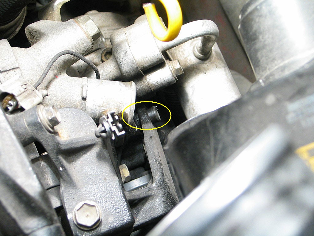
So even with the mounting bolt removed, the compressor cannot be removed until the idler puller bracket is removed first.
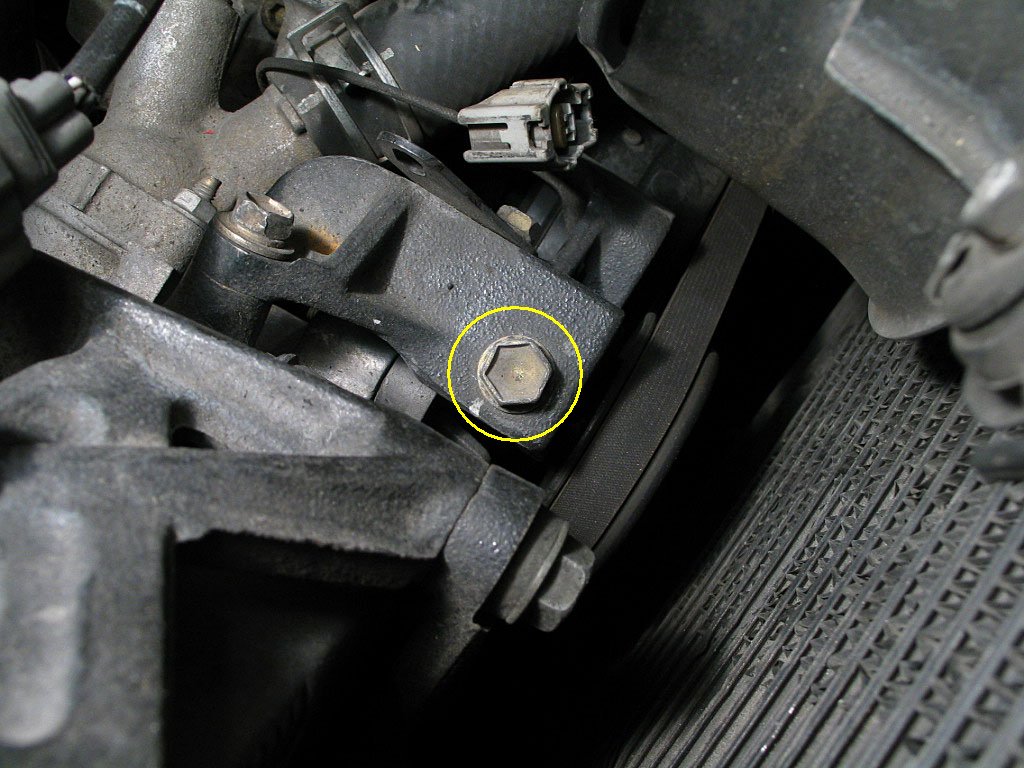
For now, just remove the 12mm bolt that secures the top leg of the idler pulley bracket. It's the one shown in the photo below.
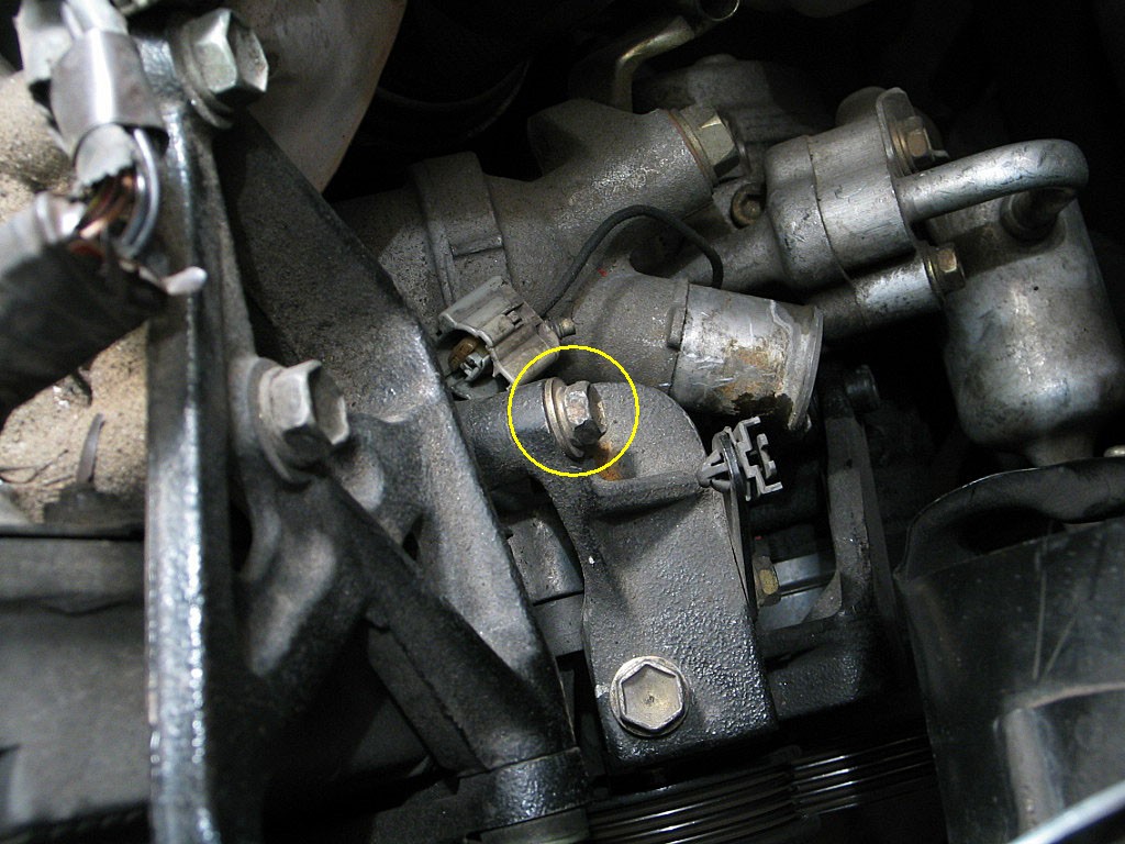
There's one more bolt, but don't think it can be removed from the top of the motor, so we'll take care of it when we remove the A/C compressor later on.
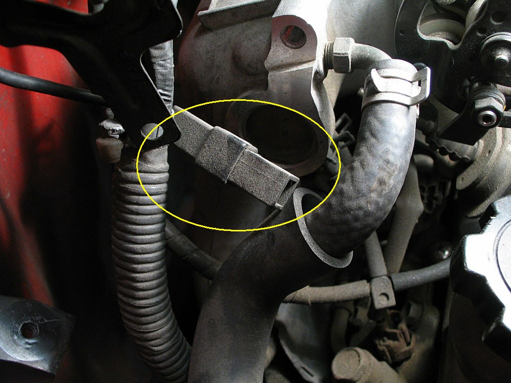
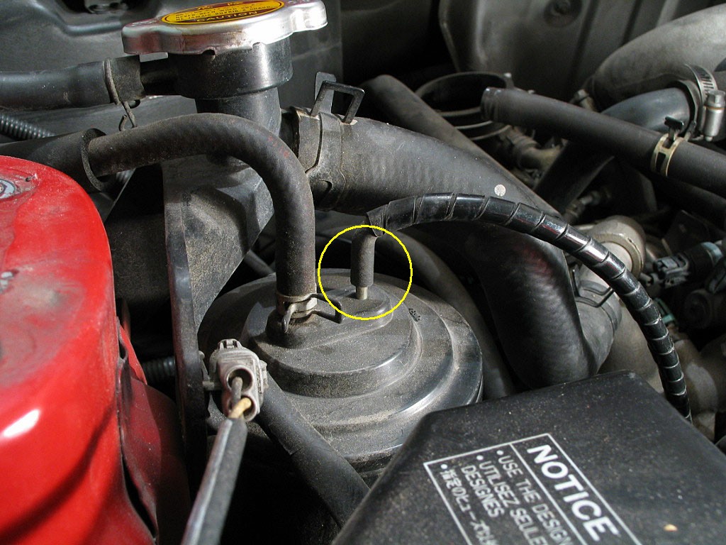
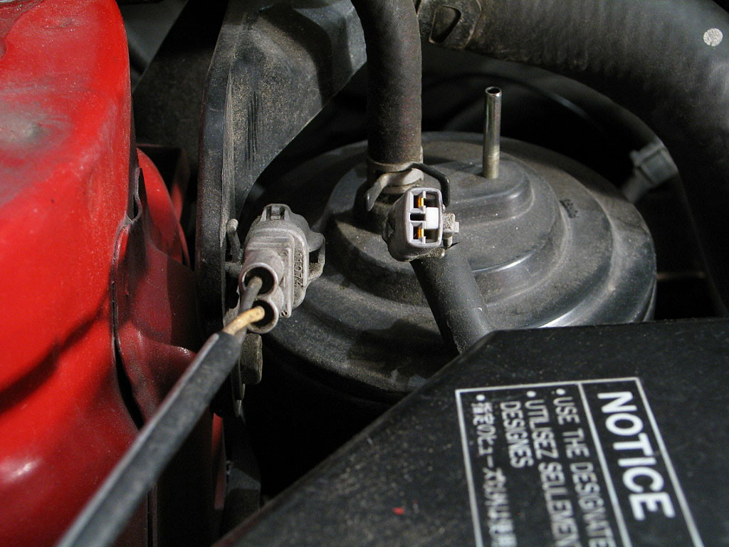
Note that my ground wire is broken, but it should go to the cylinder head. You'll need to separate the connector. You'll also need to remove the brake booster hose:
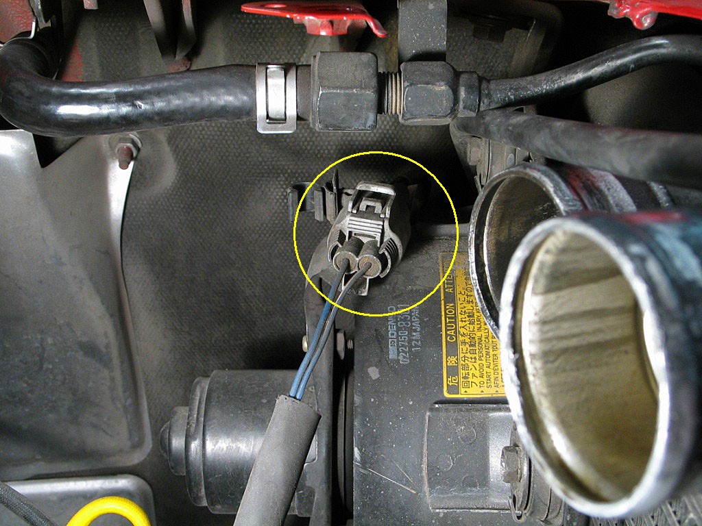
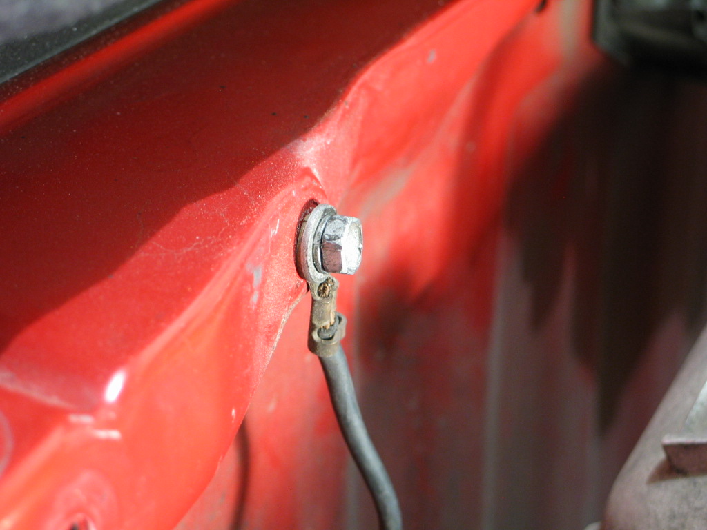
The right-rear ABS sensor connector is attached to the wheel housing:
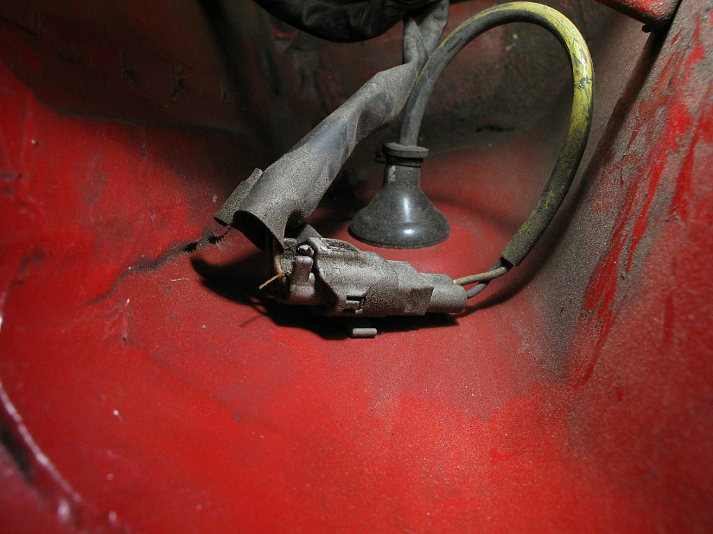
Separate the connector by pressing the locking tab in, against the housing, and then pulling the connector apart.
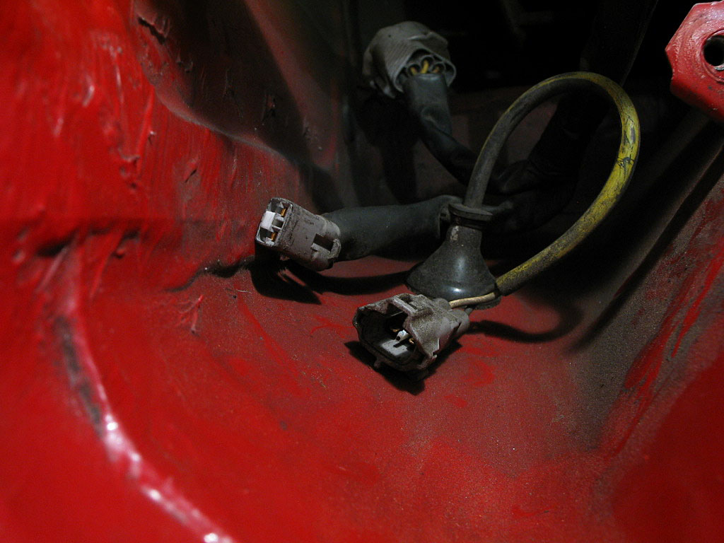
You'll also need to detach the mounting tab from the body, as the wire needs to be pulled through the opening in the wheel housing. However, that is much easier to do when the car is raised and the wheels are removed, so we'll deal with that later.
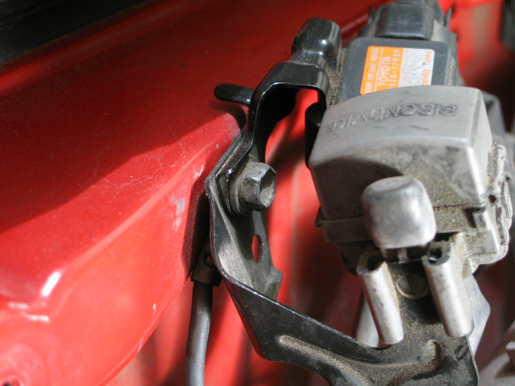
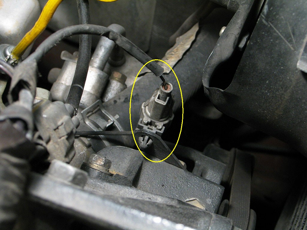
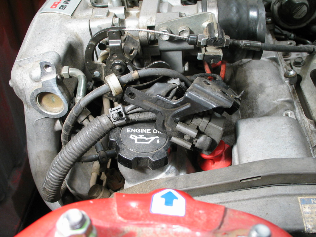
The cable to the MAP sensor should be anchored to the release latch, but mine had been detached. Here's a shot from my previous MR2:
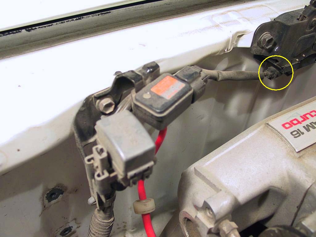
Detach the cable from the latch assembly.
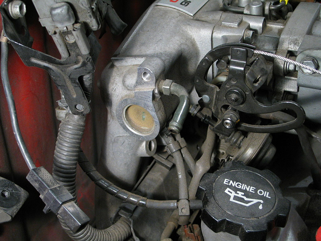
There's a single 10mm bolt securing the bracket. Remove the bolt, move the bracket out of the way, then reattach the bolt and the ground wire to the firewall:
I laid the MAP sensor and data link port on top of the cam cover:
You can also choose to remove the canister to provide a little more access to the engine mount, but it's not absolutely necessary.
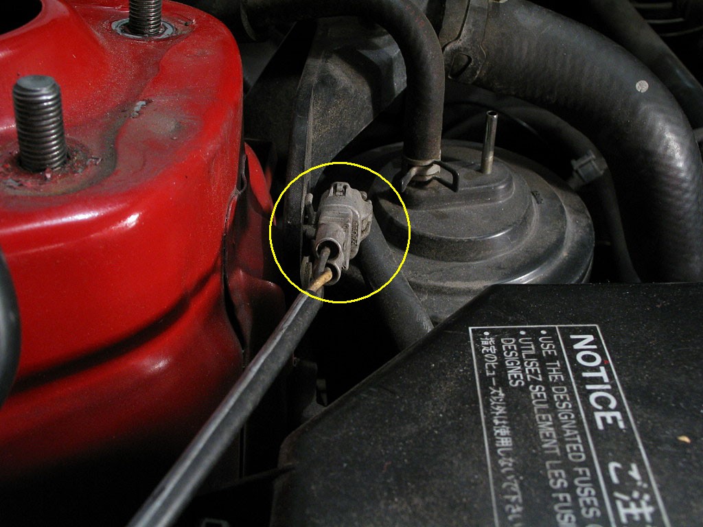
As on the right side, press the locking tab in, against the housing, and then pull the connector apart:
Using needle-nose pliers, squeeze the locking tabs together from the back side of the mounting bracket, and release the connector from the bracket: