15 September, 2004
Page ![]() 1 2
1 2
![]()
Installing a
J&S Safeguard Ultra II
The J&S knock sensor is a sophisticated black box (actually blue) that monitors your engine for knock and then retards the ignition of the offending cylinder in response. According to the manufacturer, it can respond within 1 RPM of detection, and can retard a single cylinder as opposed to all cylinders.
The original Safeguard had many advocates, and when an upgraded version was made available by ATS Racing, through a GP, I picked up the Ultra II version. This version adds a "boost retard" feature (which I'm not I'll be using) and a fuel cut defeat. I bought the higher priced Ultra II to get the fuel cut feature, since I had not yet installed a fuel cut device. I had already purchased (but not installed) an HKS FCD, but one less box is desirable. The FCD is for sale if anyone is interested.
This unit was installed as part of a larger project which included an APEXi AVC-R boost controller, GReddy Intercooler, SPAL IC fan, GReddy Oil Catch Can, and some gauges. Because of the scope of my project, some of the photos might show more disassembly than is actually required. It's also likely that the photos don't always match EXACTLY what's in the text. As is often the case, I would have changed the sequence of a few things if I had to do it over again.
Finally, remember that this is only a guide -- not gospel. What you do to YOUR vehicle is YOUR responsibility. I do not endorse, approve, authorize, or otherwise encourage you to make alterations to your vehicle. Be careful, and recognize the dangers associated with modifications to your vehicle's critical systems, like electrical, engine, brakes, etc.
Please contact me if you have comments or suggestions about the article or the project, or if you find errors on these pages.
Tools/Materials
Needed
-
Soldering iron & solder (low wattage)
-
Phillips and flat-bladed screwdrivers in various sizes
-
10mm and 12mm sockets with assorted extensions
-
Sharp Xacto knife or similar cutting tool
-
Wire cutter/stripper tool
-
Electrical tape
-
Assorted wire ties
-
Ribbed cable sleeving (Optional)
-
Braided cable sheathing (Optional)
-
10 feet of 22 AWG hookup wire in 7 or 9 different colors (Optional)
Doing It
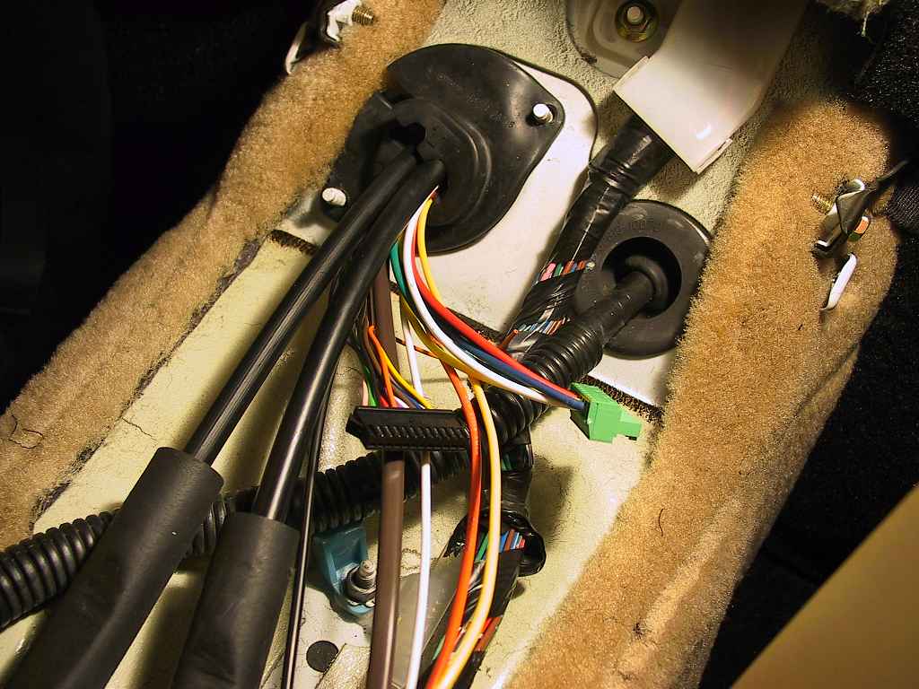
I chose to mount the control unit in the upper compartment of the
rear console. Here's a photo of the finished installation:
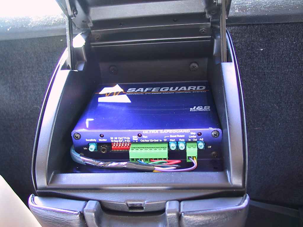
This location was perfect for me. The unit fit just right, with enough
room at the rear to install the vacuum/boost line. Since the wires come
into the cabin through a bulkhead grommet just below the console, it meant
I didn't need to run wires to the dash. I DO plan on running the LED
monitor wires to the A-pillar gauge pod when I receive the monitor unit,
but that's probably only one or two wires.
I used some Velcro strips to keep it from sliding around. Just a few hold
it tightly in place.
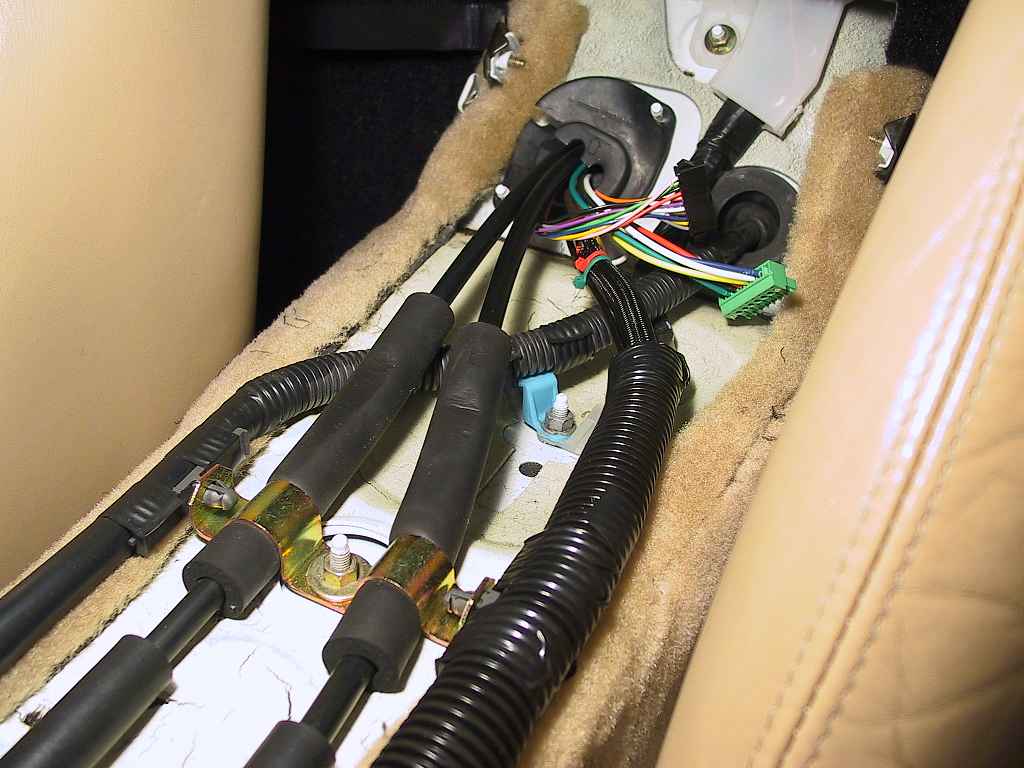
Routing Wires Through the Firewall
I had 7 wires for the Safeguard control unit, 6 wires for the AVC-R control, 3 wires for the IC fan switch, 2 wires for a future EGT gauge, plus a boost hose. This was going to require some serious work to get these through the firewall without opening more holes.
I enclosed each bundle of wires in a braided cable sheath. This is an expandable cable sleeve perfect for routing groups of wires. It comes in a variety of sizes and colors, although it is fairly expensive (about $3 to $5 per 10-foot length for the sizes I used). It's available at McMaster-Carr as "Braided Polyethylene Mesh Sleeving".
The braided sheath is fine for most uses, but is not suitable for protecting the wires inside the engine compartment. For this, I used what the factory uses - ribbed sleeving. You can buy this at several sources, but McMaster-Carr carries all different sizes. It's called "Slit-Convoluted Polyethylene Conduit" in their catalog. I had purchased several sizes over time. Unfortunately, McMaster-Carr only sells this is 25' lengths. Fortunately, the smaller sizes are what you need, which reduces the cost.
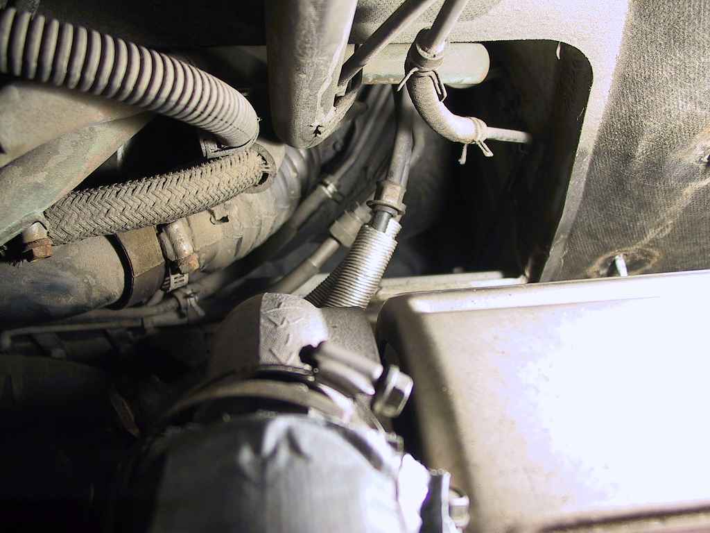
Once I had prepared the wire bundles, I had to choose an opening in the
firewall. The first task was to remove the rear and center consoles in the
cabin.
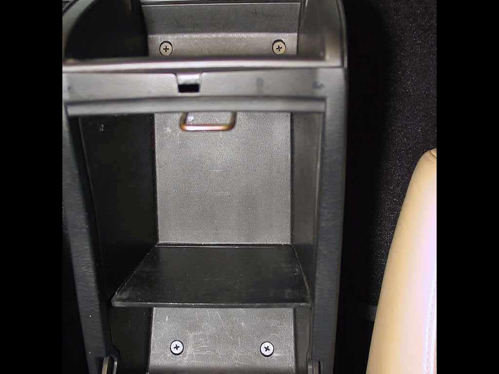
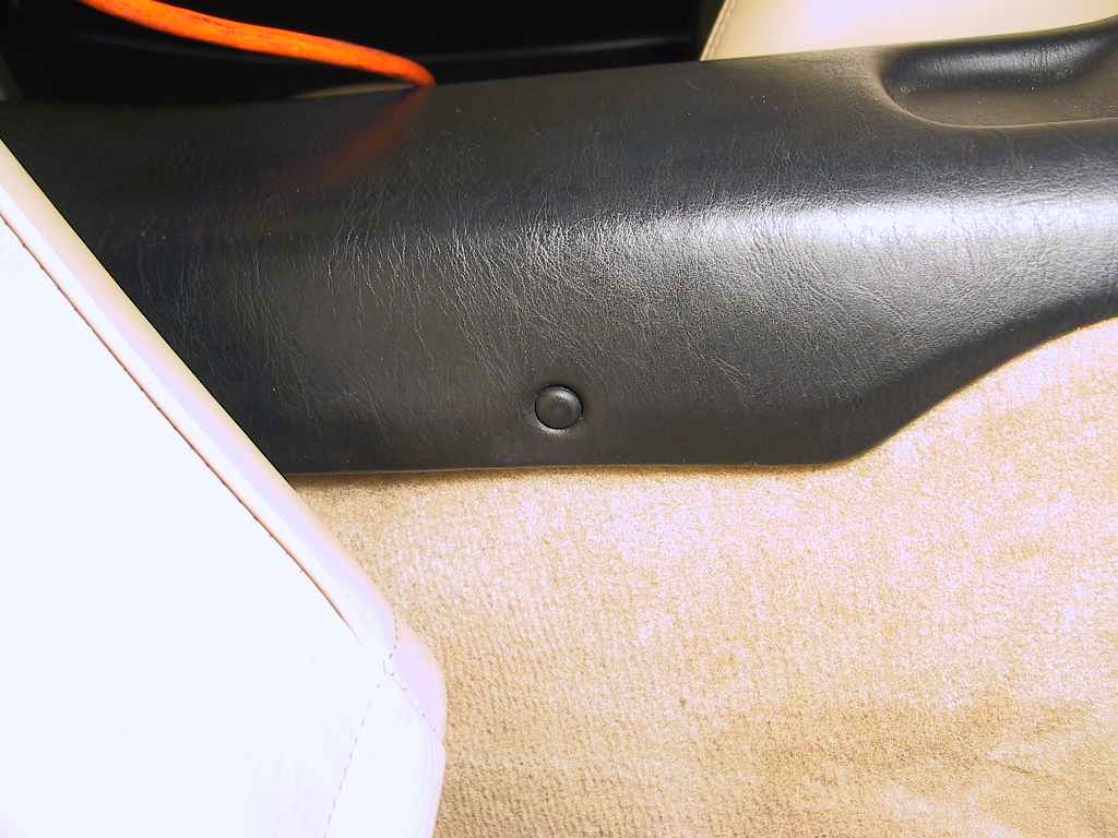
Using a small, flat-bladed screwdriver, slip the blade behind the plastic cap and ease it off. They are quite secure, so be careful not to damage the console in the process.
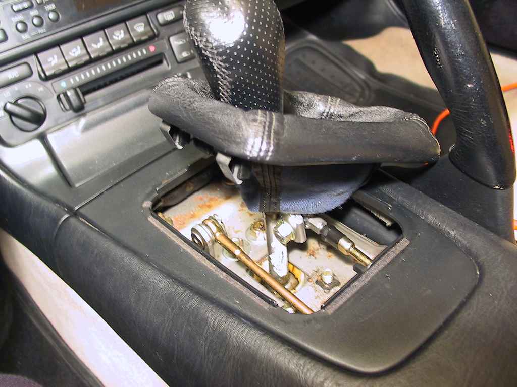

I chose to remove the shifter knob to get things out of the way, but it's not a requirement.
Looking at the previous photo, you'll notice two Phillips screws on a metal brace at the front of the console. Remove these screws and the console should come free.
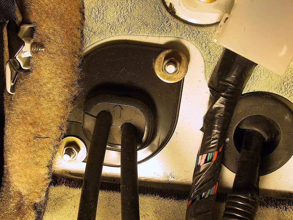
This seemed to have some room for additional cables, if I drilled or cut some additional passages through the grommet.
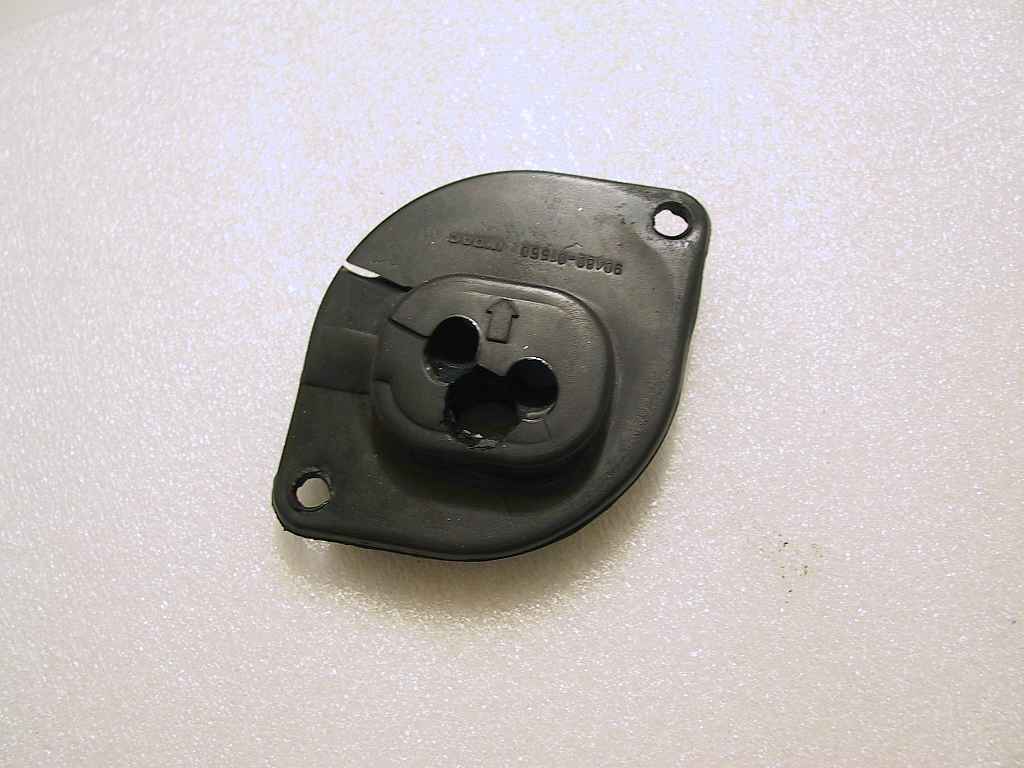
I could tell that I would need to grind away a bit of the metal cap to avoid stressing the wires, but it looked like this would work.
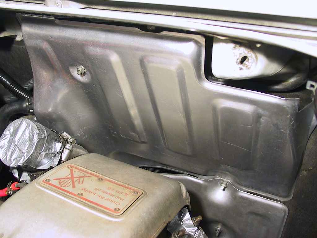
In my case, I had already removed the intake assembly and the turbo-to-intercooler pipe. You'll need to remove the intake assembly at a minimum, and removing the intercooler pipe will gain access to the heat shield fasteners.
The heat shield consists of two metal panels, held on with 10 mm
nuts/bolts. While they are difficult to reach (this is an MR2,
remember), I managed to get them all removed. Here are a sequence of
photos which show the mounting points:
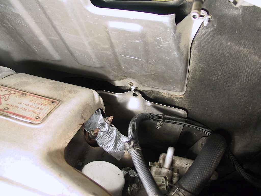
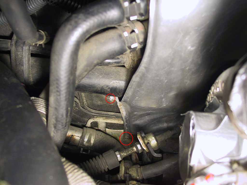
There is a remaining nut that I could not get a photo of, which is
located directly below the turbo. While the nut was not impossible to
reach, the problem was that the larger (upper) heat shield panel had an
integral stud attached. This stud prevented the panel from being
removed, as the shifter cables were blocking it.
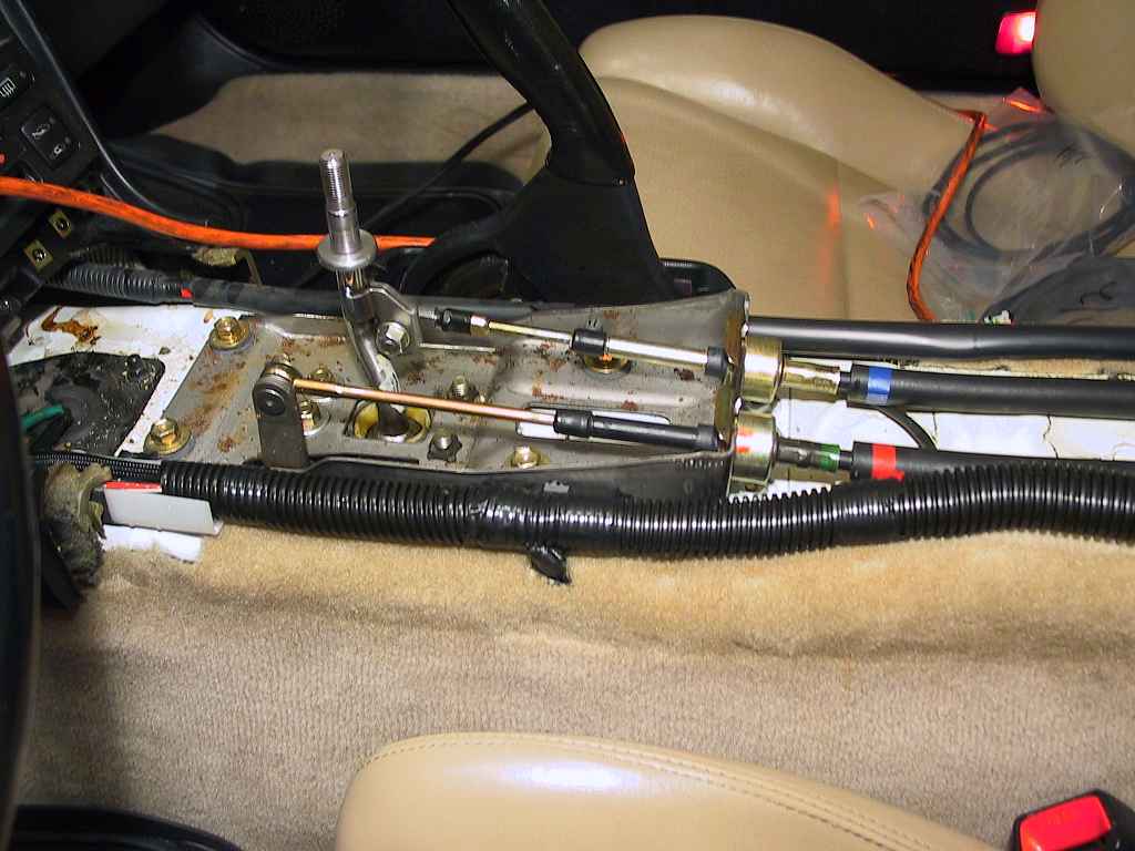
I messed around with this for about an hour before I decided to
jack the car up and loosen the shifter cable bracket from underneath.
Here's the location:
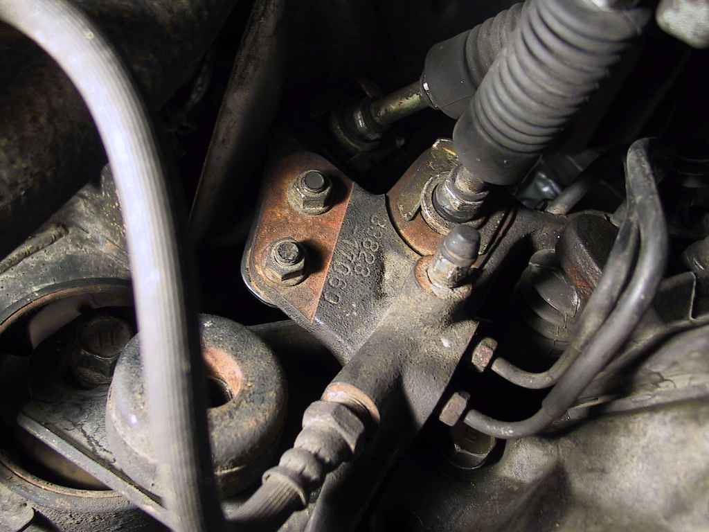
There are two 12 mm nuts attaching the bracket. Once these are removed,
you can lower the car and move the cables out of the way of the heat
shield stud.
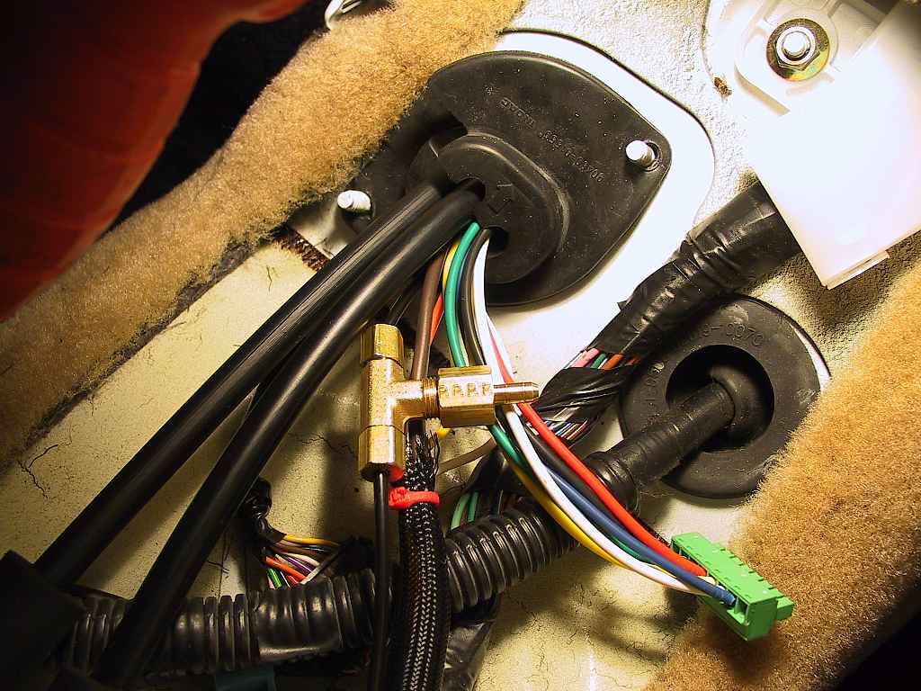
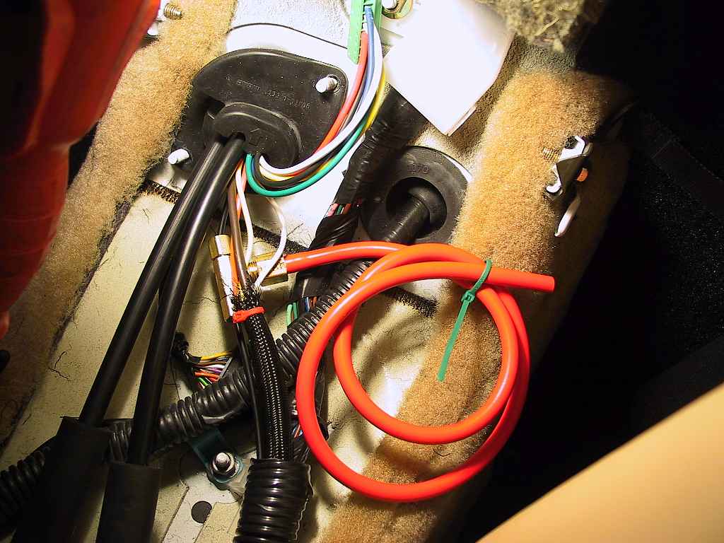
This hose will attach to the back of the Safeguard unit.
The connectors supplied by J&S made it simple to remove it
from the 18 AWG wires and reattach to the 22 AWG wiring. I pulled
through enough of the wiring harness to ensure I could reach the
Safeguard control unit after it was mounted in the top of the rear
console. I then turned my attention to the wiring in the engine
compartment.
Page ![]() 1 2
1 2
![]()