Page        1    2      


Replacing Struts & Springs
(continued)

Once the rears were finished, I proceeded on to the fronts, where trouble was brewing. I'm going to skip the parts that are the same as in the rear, and concentrate on the differences. 
 

As always, observe safety rules. Make sure the rear wheels are chocked, and that jack stands are positioned properly. I jacked up the front under the front crossmember, and placed the jack stands under the side jacking points.
 

If you religiously follow Toyota's BGB, you'll be prompted to remove the ABS speed sensors. Here's a photo:
103-0346_IMG.JPG (201811 bytes)
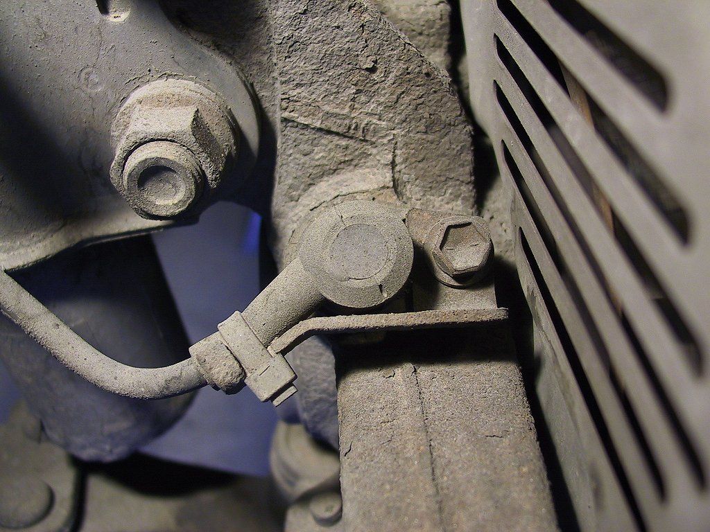
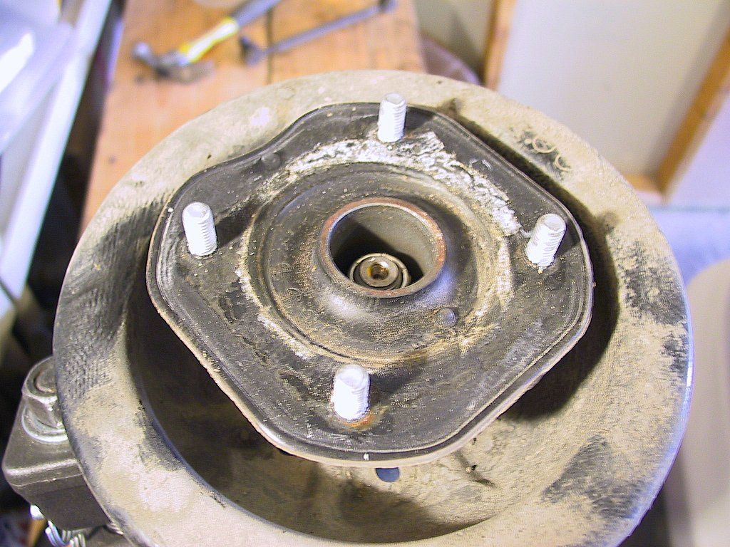
It doesn't look too hard, a 10mm bolt holding the sensor on to the front hub. However, some vital information is missing from the BGB:
  • The sensor case is made of plastic, with a metal plate to secure it to the hub.

  • It's inserted into a hole, probably rusted in place.

  • Replacement cost (list price) is more than $115.00 each.

  • It doesn't need to be removed, if you are careful.

If only I'd left them in place....
 

OK, I managed to work the first one loose, and here's the result:
103-0348_IMG.JPG (191475 bytes)
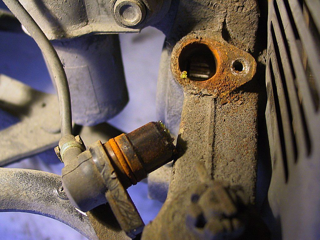
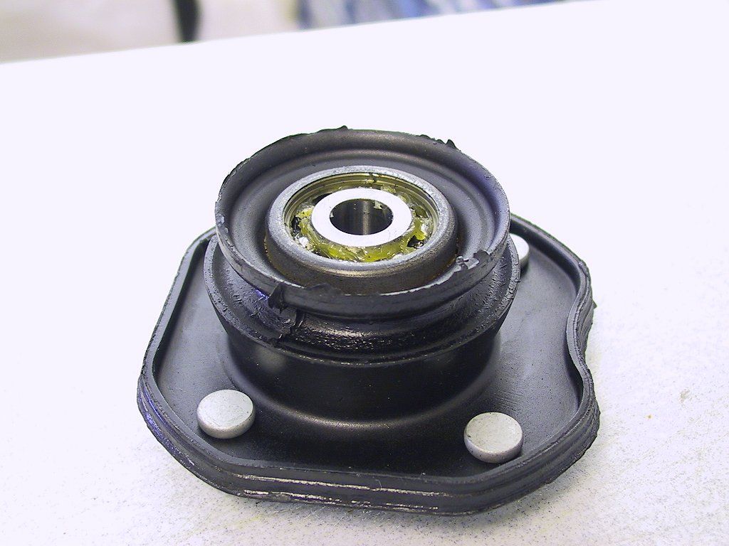
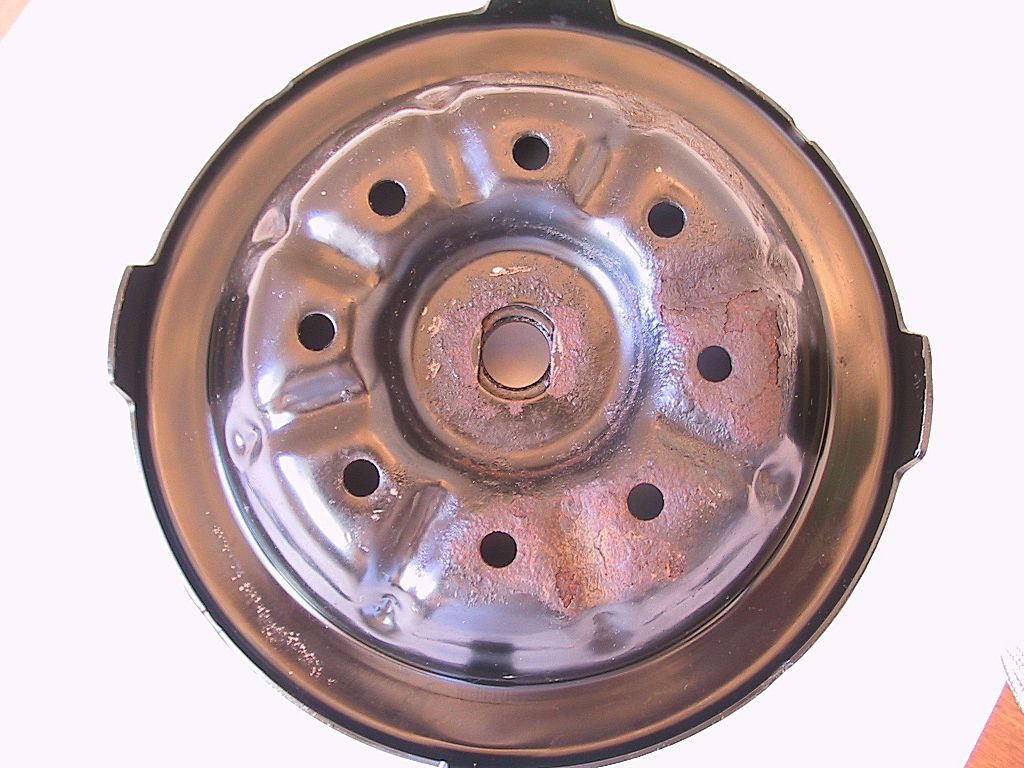
I plugged the hole up to prevent rust scale from dropping down into the hub. I then used WD40 to remove the loose rust around the opening. After that was fairly clean, I cleaned out the hole. I knew I would need to fit a new O-ring. Unfortunately, upon closer inspection, I discovered the mount was cracked. Worse, the other sensor broke completely in two during removal. I ended up replacing both units. A very costly learning experience.
 
Next, I used a 10mm socket to remove the clamp holding the line to the sensor:
103-0350_IMG.JPG (147143 bytes)
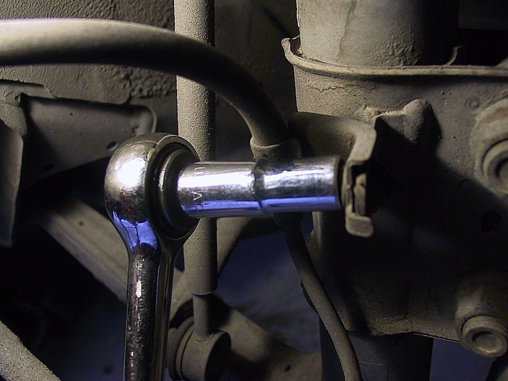
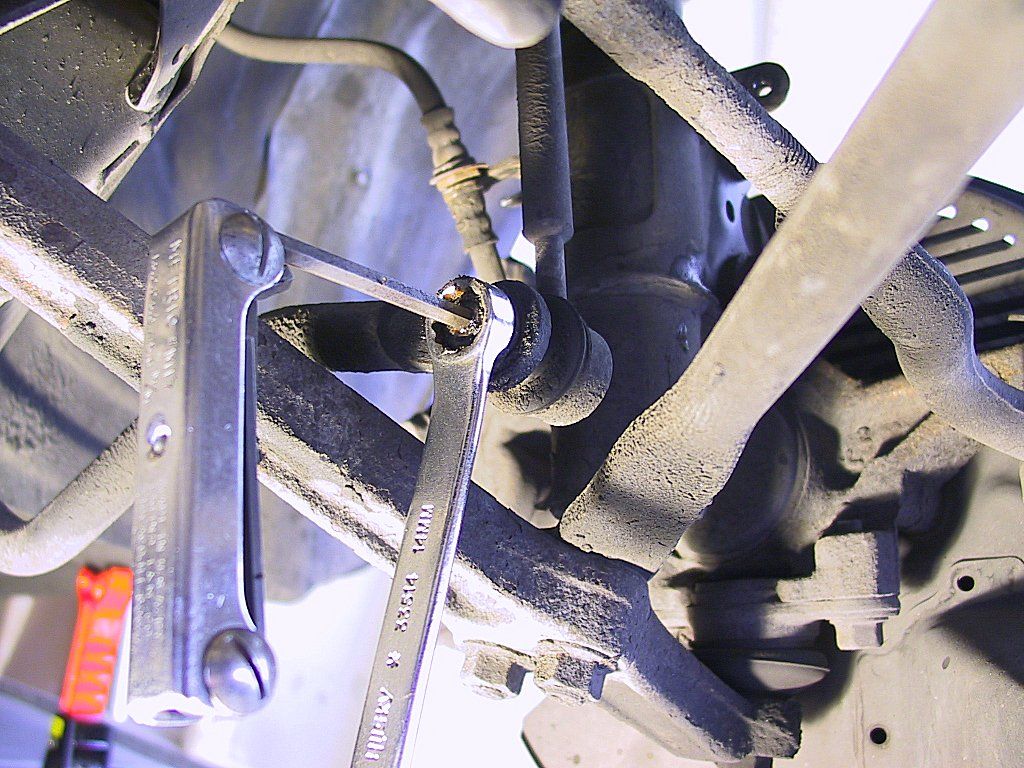
You can tie the sensor out of harm's way somewhere. It's likely all you really need to do is remove this nut to provide enough slack in the cable. 
 
In the front, it's very tight quarters trying to remove the upper stabilizer link bolt. I found it much easier to disconnect the link at its lower mount, and simply leave it connected to the strut tower. You have plenty of access, and can remove it later when the strut is out of the car and mounted in a vise. 
103-0358_IMG.JPG (201822 bytes)
 
Once all the components have been removed, I found it easier to remove the front strut unit than the rear. This is mainly due to the larger spring perch. I was able to use a jack handle as a brace to compress the lower spring perch:
103-0372_IMG.JPG (212381 bytes)
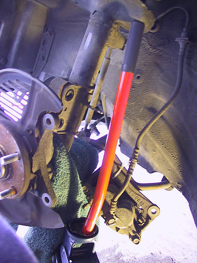
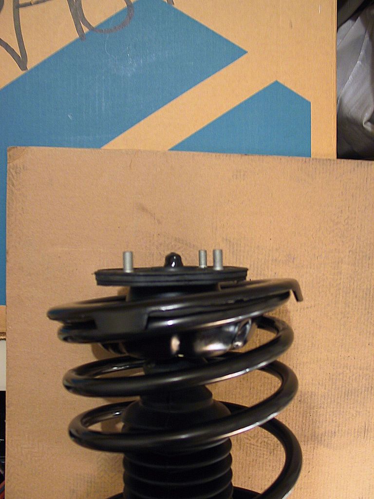
Once the spring was compressed slightly, I was able to work the hub off, and remove the strut assembly.
 
After getting the strut mounted in the vise, I attempted to remove the upper stabilizer link mount. 
103-0380_IMG.JPG (197868 bytes)
I ran into trouble right away. The mounting bolt would not come off, and I ended up stripping out the internal hex-shaped hole in the stud. This probably was due to my not being patient enough to let the penetrating solvent do its job. 

There's really no need to remove this upper mount anyway, as long as you don't damage the link while working on the strut assembly.
 
I used a pair of long-nose vise-grips to hold the stud from behind the mount:
103-0381_IMG.JPG (122428 bytes)
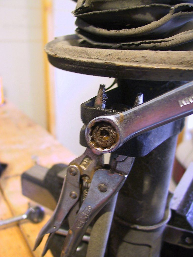
This is NOT the recommended removal method, but it worked. However, since I was facing the same problem when reinstalling, I decided to order a new link. 
 
As you can see in this photo, the strut boot is in seriously bad condition:
103-0383_IMG.JPG (215089 bytes)
I'm sure this was a factor in my subsequent problems.
 
The front strut mounts are just a bit different from the rears. As in the rear, you'll need to remove the 19mm nut at the top of the strut rod:
103-0388_IMG.JPG (197829 bytes)
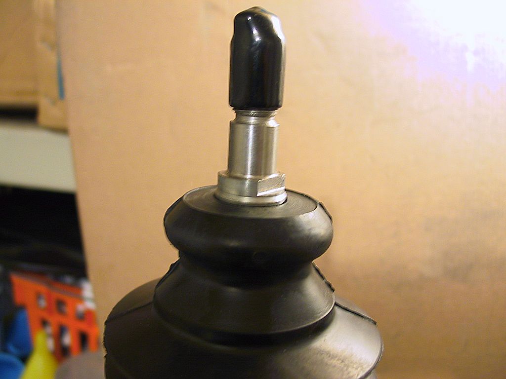
If you loosened this while the strut was still in the car, this nut should come off easily.
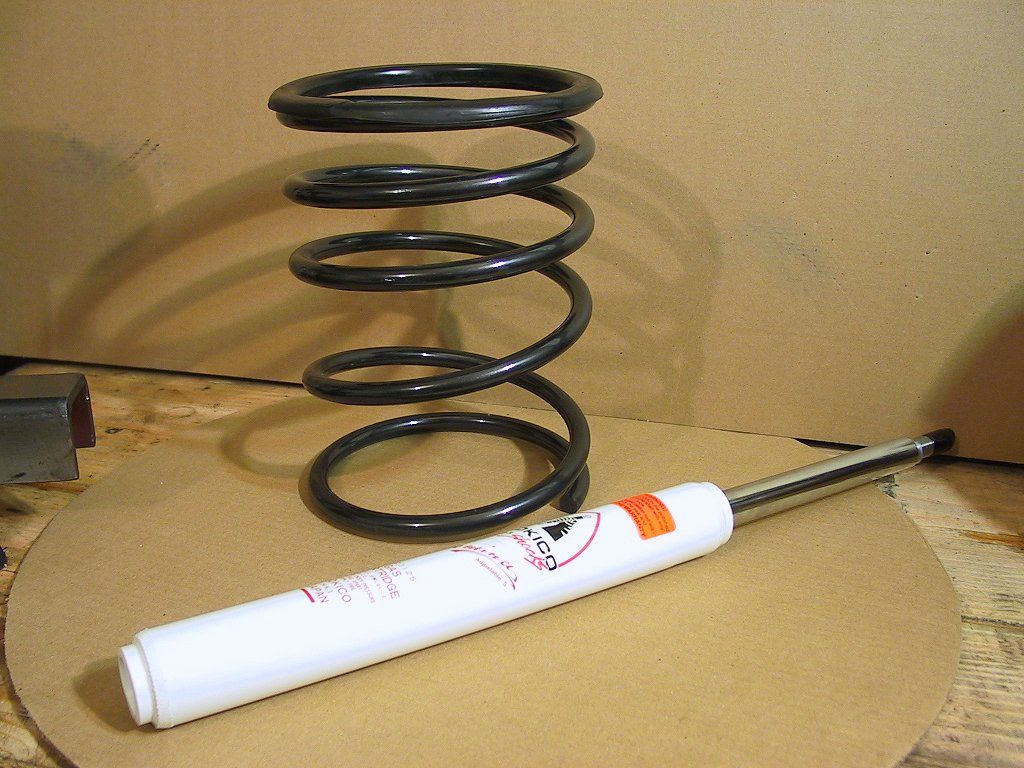
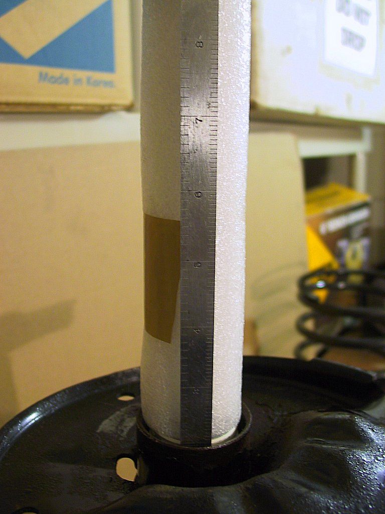
 
Unlike the rear strut mount, there is no spacer below the strut rod nut. Instead, you'll find the inner sleeve of a ball bearing. The bearing is encased in a hard rubber mount. Here's a photo of a brand new one:
104-0452_IMG.JPG (115309 bytes)
 
At this point you should be able to pull off the upper strut support and spring mount. I was not so lucky. On both front struts, the supports had become rusted/corroded to the strut shaft. I'm sure the poor condition of the strut boots contributed to the problem.
 
With great difficulty, I was able to hammer one of the supports off, but the bearing was not in good shape. No amount of cleaning and re-packing with grease could remove the notchy feeling as I rotated the inner bearing sleeve. A new mount (with bearing) was needed.
 
On the other strut, I simply gave up, as no combination of penetrating oil and hammering would loosen the mount from the strut shaft. As a result, I ended up ordering both the strut mount and the spring support. 
 
Removing the the spring and strut cartridge was identical with the rears, with the exception of a rubber "washer", or cushion, on the top of the spring. You can click here to refer to the procedure on the rears.
 
Here's a photo of the new spring and strut: 
104-0418_IMG.JPG (152031 bytes)
 
I poured a bit of fork oil into the strut body, then slowly lowered the Tokico inside. I used a thin steel ruler to determine the oil level: 
104-0444_IMG.JPG (126557 bytes)
Tokico recommends the level at 1½" to 2" below the edge of the housing. I'm speculating that too much oil would make it impossible to tighten the gland nut all the way.
 
The procedure for tightening the gland nut was the same as in the rear. As before, I used some packaging foam to protect the shaft:
104-0440_IMG.JPG (143514 bytes)
 
Next, I installed the new boot. It's held on to the strut body with a long cable tie.
104-0467_IMG.JPG (95340 bytes)
 
The strut rod has two flats on the shank...
104-0465_IMG.JPG (74591 bytes)
 
...that mate with matching flats on the upper spring perch:
105-0597_IMG.JPG (123352 bytes)
 
Install the spring, then fit the upper spring perch onto the flats of the strut rod. Place the bearing dust seal over the shaft, finally fitting the upper strut mount.
 
The strut rod nut is next. The BGB indicates 36 ft. lbs. of torque.

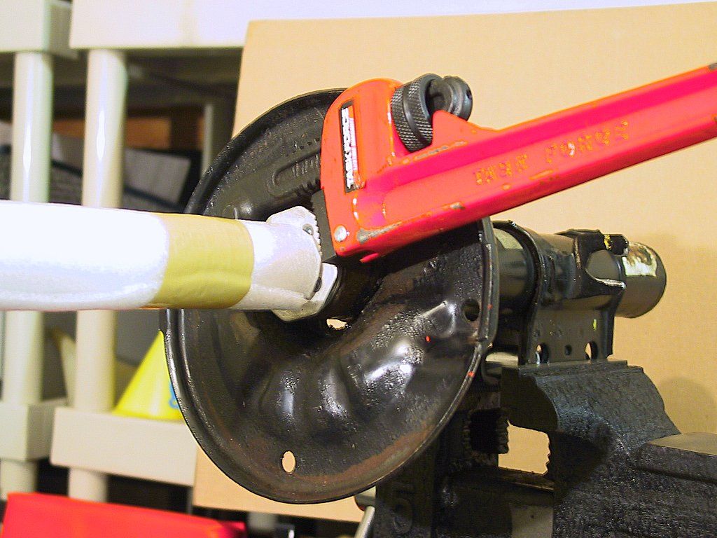
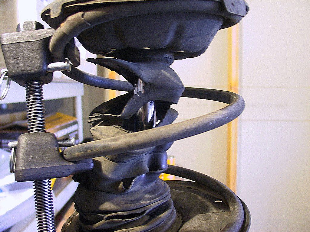
It's unlikely you'll be able to keep the upper spring perch from rotating as you tighten the rod nut. I thought that I could get it as tight as possible, then install the assembly into the car, then apply the final torque after everything was assembled. Sadly, even after the weight of the car was on the assembly, the spring perch still wanted to spin out of position when applying torque to the nut.

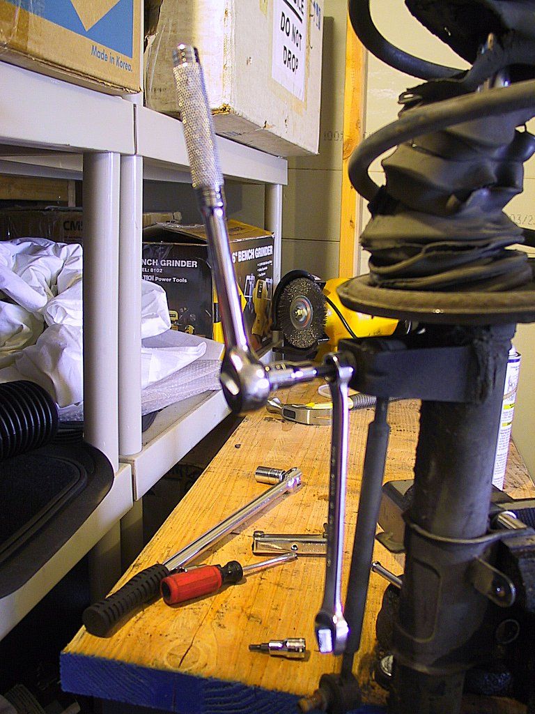
Since I didn't have an SST to use, and the perch was too large to fit in the vise, I went searching for a tool that could solve my problem. Luckily, I found it at Harbor Freight -- a long pair of needle nose pliers, with the tips bent at 90º:
105-0585_IMG.JPG (65488 bytes)
 
These only cost me $7.00. The tips fit into the underside of the spring perch, as shown here:
105-0592_IMG.JPG (62917 bytes)
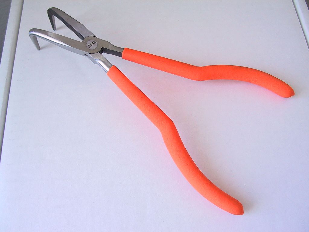
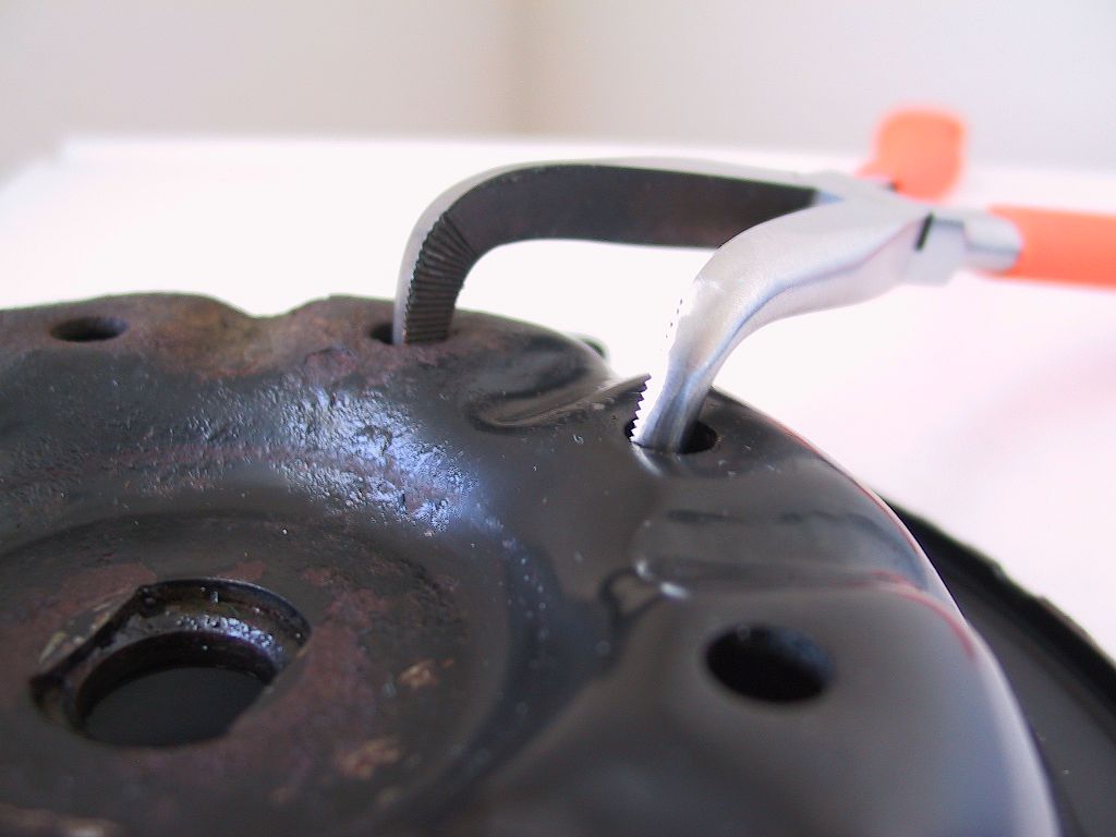
Although these photos show the pliers prior to assembly, in reality I used them with the strut already mounted in the car. The only problem was needing a helper to tighten the nut while I held the perch in place.
 
An added bonus to the pliers is they permit you to align the upper perch on the strut. If you look at the assembled strut, the upper perch sits at an incline to the cartridge:
104-0460_IMG.JPG (116293 bytes)
 
The perch is marked for correct alignment, as shown here:
104-0456_IMG.JPG (149151 bytes)
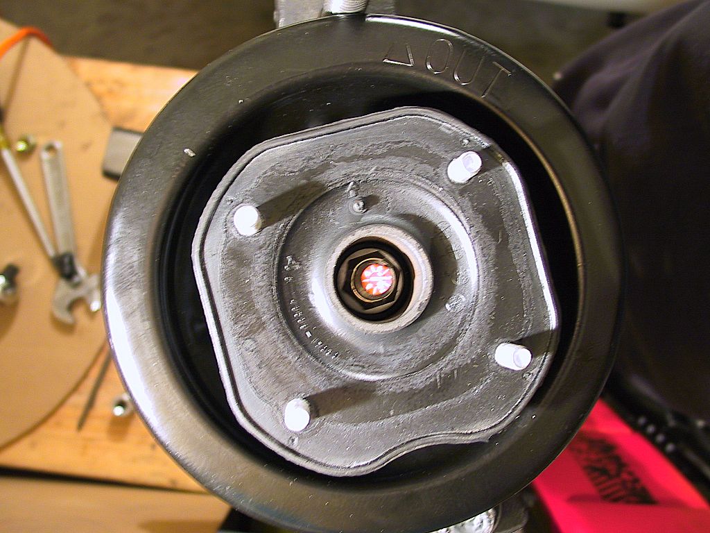
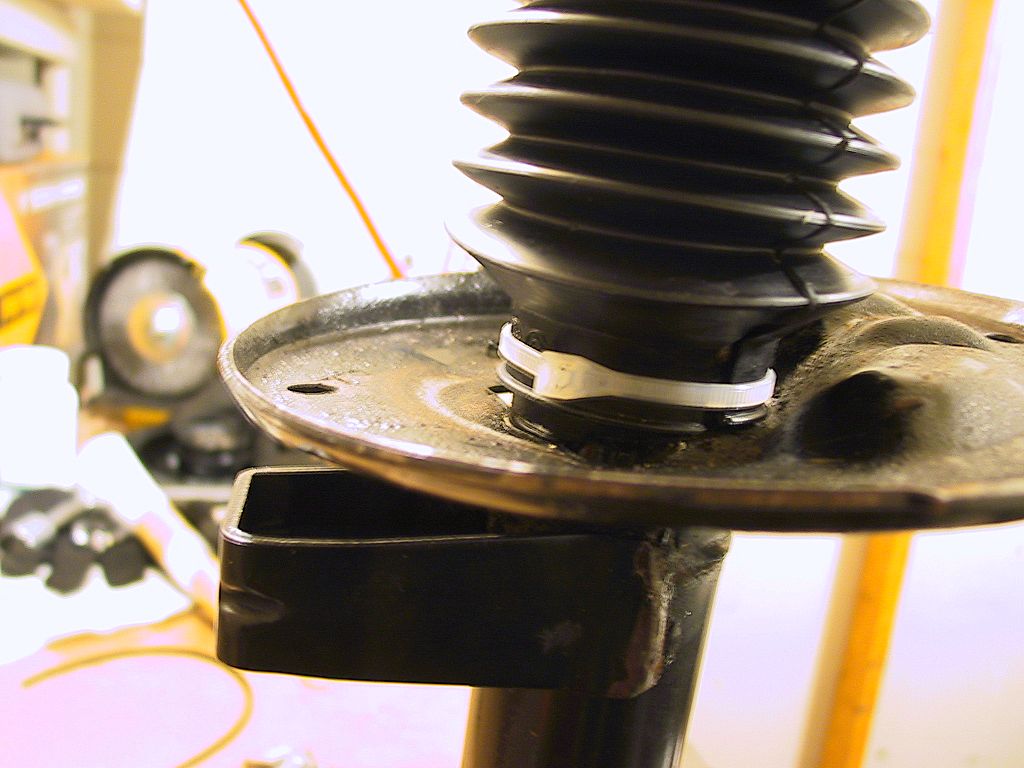
If you look closely, you'll see the word "OUT" stamped into the rim of the spring perch. This corresponds with the middle of three flanges on the edge of the perch. The BGB says to have this pointing to the outside of the car. However, it will be close to impossible to keep it properly aligned during installation, and the bent pliers can easily reposition it after installation.
 
The remaining installation details are fairly straightforward, being the reverse of assembly. In my case, I installed new ABS speed sensors as well, but they were a breeze compared to removing the old ones.
 
It should be obvious that a four-wheel alignment will be required once everything's back together. I told the alignment shop that they should carefully check everything, and the results were rewarding, The car now handles like a dream.
 

      Page        1    2      

Dave Martin
1993 MR2 Turbo