15 September, 2004
Page ![]() 1 2
1 2
![]()
Replacing Struts & Springs
In December, 2000, I replaced my MKII's springs with Eibach's Pro Kit progressive springs, and the stock struts with Tokico Illumina 5-way adjustable strut cartridges. I relied heavily on the BGB and other owners' "help sheets" to accomplish this. The resulting procedure should help anyone else contemplating this installation for the first time. Keep in mind that it's aimed towards the first-timer.
This is a major undertaking, at least in time required, but not an overly complex one. The BGB is of limited help, because several significant tips are missing, and because the BGB tends to be very narrowly focused. However, for torque settings it proved helpful, if occasionally erroneous.
Hopefully, the photos will assist in areas where text fails miserably. Some are well-focused, but others are a bit fuzzy. I hope all are helpful. It was a brand new camera at the time, and I am a novice photographer. The images are 1024x768, but I thumbnailed them to help the pages load faster. Clicking on any of them will take you to the full size image.
Finally, remember that
this is only a guide -- not gospel. What you do to YOUR vehicle is YOUR
responsibility. I do not endorse, approve, authorize, or otherwise encourage
you to make alterations to your vehicle. Be careful, and recognize the dangers
associated with modifications to your vehicle's critical systems, like
electrical, engine, brakes, etc. Please contact
me if you have comments or suggestions about the article or the project, or
if you find errors on these pages.
Tools
Needed
-
Floor jack (larger is better) or lift
-
Jack stands
-
Wheel chocks
-
1/2" drive metric socket set with extensions and breaker bar
-
3/8" drive metric socket set with extensions
-
Metric combination wrench set
-
5mm Allen wrench
-
Torque wrench capable of 20-130 ft. lbs.
-
Various sizes of Philips and flat screwdrivers
-
McPherson strut spring compressors
-
Large (5" minimum) machinist's vise on sturdy workbench
-
Long needlenose pliers with bent tips
-
Lightweight general purpose oil
-
Hacksaw
-
Long cable ties
-
Thick bath towel
The following tools are recommended but not mandatory:
-
Grinder with wire wheel
-
Dremel Moto-tool with abrasive wheel
-
Cleaning solvent (carburetor cleaner or general degreaser)
-
Oil pan (to catch waste oil)
-
Chalk or marker
Before You
Start
Make sure you know how to use a coil spring compressor, and follow safety guidelines, as these compressors can be deadly.
Make sure you have some time to spend. I won't admit to how much time this project took, but there were some problems along the way and I interrupted work to take photos (which requires cleaning your hands each time). I ended up ordering some additional parts from Toyota before I could complete the entire job, but even so this is a full day's job (or more) if you are working alone. Don't rush it!
Also, I strongly recommend using 6-point sockets and box wrenches on all nuts and bolts heads. Many of these fasteners will likely not have been removed in a long time, and unless your car has lived its life in a dry climate, rust and corrosion are likely.
Doing It
I started with the rear. Click here
to jump ahead to the front wheels. Place wheel chocks in front and back
of the front wheels. Loosen the wheel nuts on both wheels, then release
the parking brake. I jacked up the car in the center of the rear
crossmember. I set jackstands at the jacking points of the door sills.
Remove the wheel from one side. On my rear brake rotors,
there were ten (10) holes for the wheel studs. Mark one of the holes where
the stud protrudes to indicate which ones to line up afterward. I had
problems during reinstallation, and changing the orientation of the rotor on
the lugs cured it.
It's helpful to screw one of the wheel nuts back on to keep the rotor in
place. Since the rotor is only held in place by the wheel nuts and the brake
caliper, it might tend to fall off later when you remove the caliper.
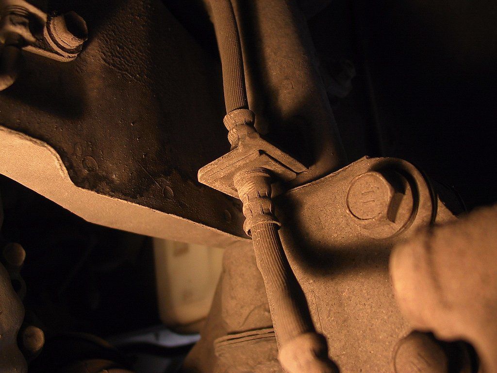
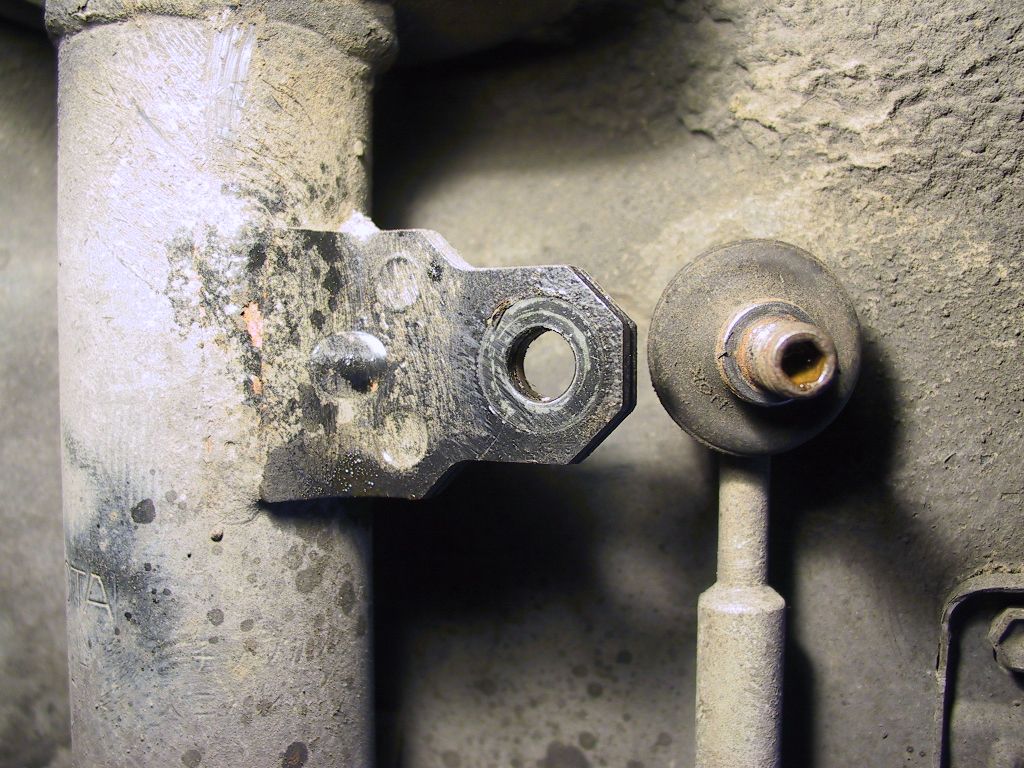
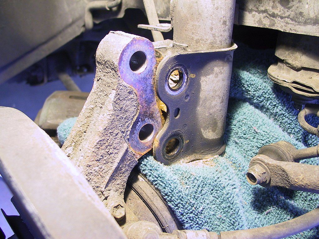
The BGB says you need to disconnect the brake line, but there's a way
around that. You'll need to cut a slot about 3/8" wide in the hose
bracket on the strut body. Here's the bracket before cutting:
First, remove the U-shaped clip from the underside of the bracket to free
the hose joint.
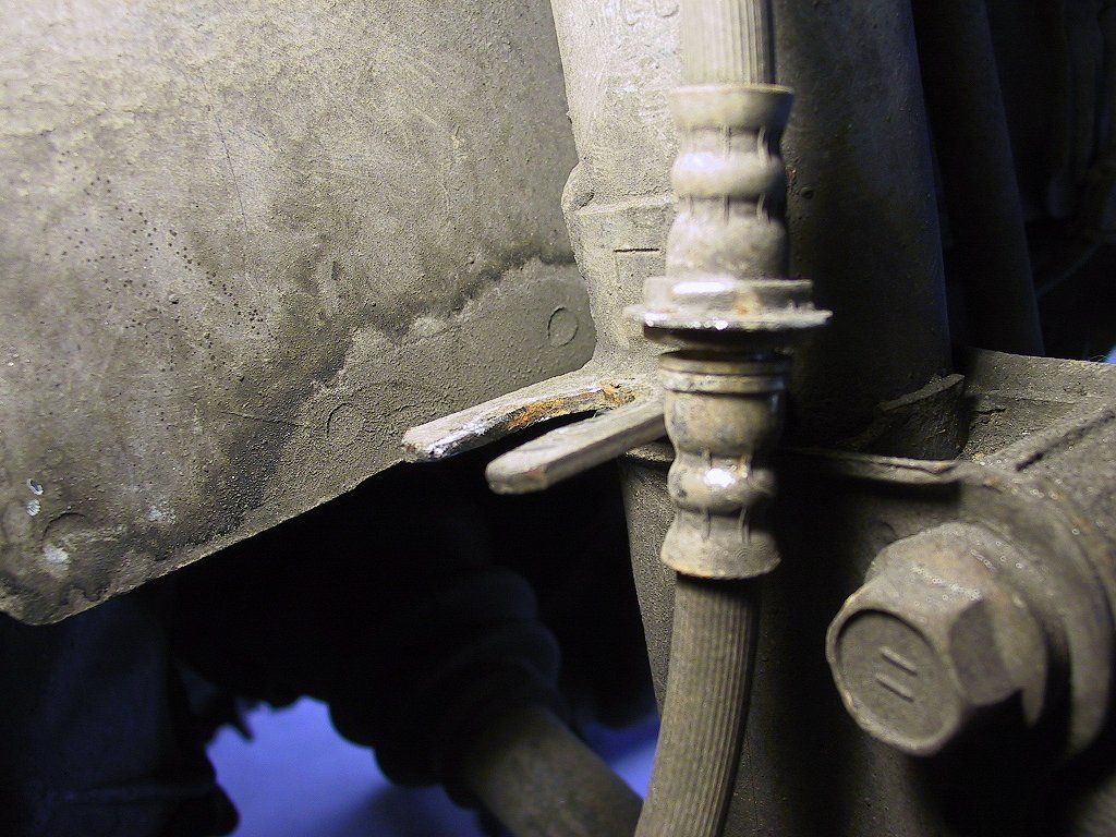
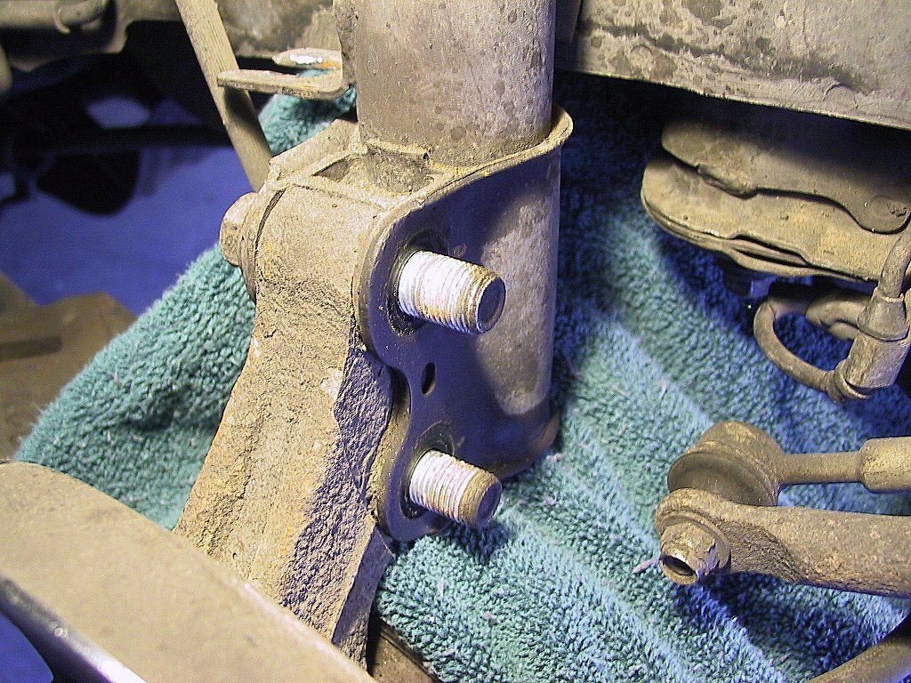
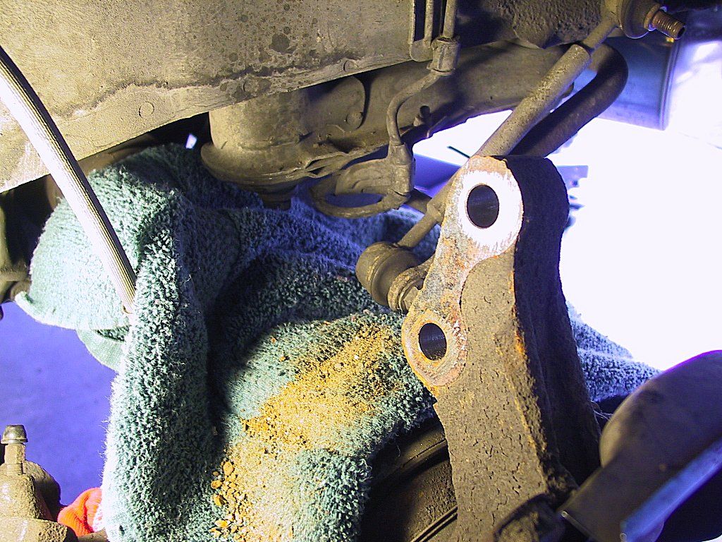
I tried using a Dremel moto-tool to cut the slot, but it was not up to the
task. After two broken bits and minimal progress, I found I could actually
get a hacksaw in there, and that made quick work of the cutting. I used the
Dremel with a grinding wheel attachment to smooth the edges of the cut
afterward. Here's the view after:
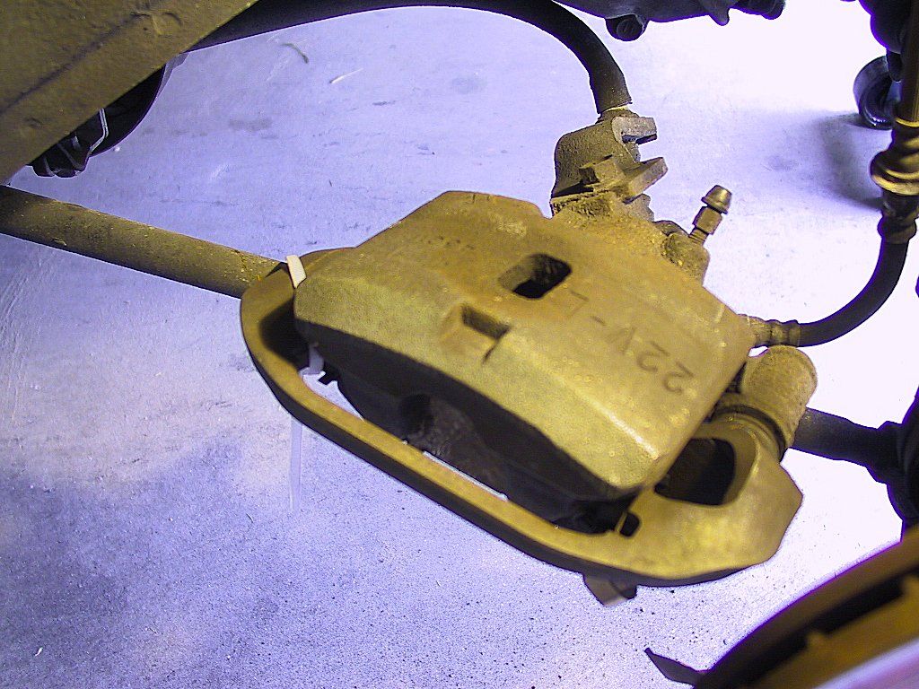
Next, you'll need to remove the brake caliper, something which the BGB
neglects to mention. There are two 17mm caliper bolts on the back side of
the hub. I needed a long breaker bar to loosen these bolts. As you remove
the second bolt, the caliper might try to slip off the rotor, so be ready to
catch it to avoid stressing the brake hose. I used a cable tie to attach the caliper to the tie rod:
You might need a couple of ties to keep it secure and not suspended by the
hose. Remove the rotor and set it aside.
You'll need to remove the upper mounting bolt on the
stabilizing link. I recommend strongly that you soak the nut with penetrating
oil prior to the removal. It's quite easy to damage the stud if you don't.
Fit a 14mm box wrench on the nut. I recommend a 6-point wrench, but I didn't
have one, so I used a 6-point socket to break the nut free. After I'd loosened
the nut a tiny bit with the socket, I replaced the socket with a box
wrench.
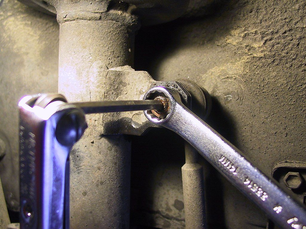
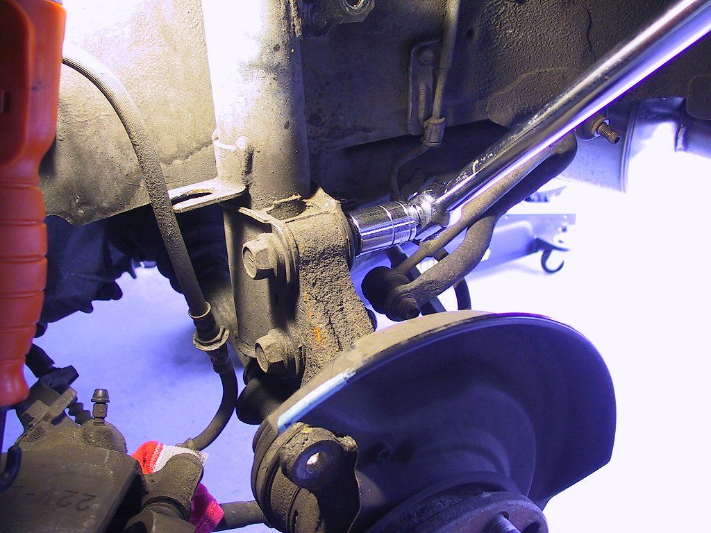
The stud has a 5mm hexagonal hole in its shaft to enable fitting an Allen wrench
to prevent it from turning with the nut. Make sure it's cleaned out so you can
get a good grip with the Allen wrench, as shown here:
It's common for the nut to loosen a bit, then jam up as you try to remove it
entirely. If you strip out the internal hole, you can get a grip on the stud
from behind the bracket with a pair of thin-nose pliers or vise-grips. Be very
careful, though, as I ruined one of the studs this way (more on that later).
If the bolt is reluctant to loosen, try removing the lower bolt instead. You can
remove the top one later after the strut has been removed.
If the stud won't clear the bracket, or if there's too much tension/compression on the link, leave it alone until you are ready to remove the strut later on.
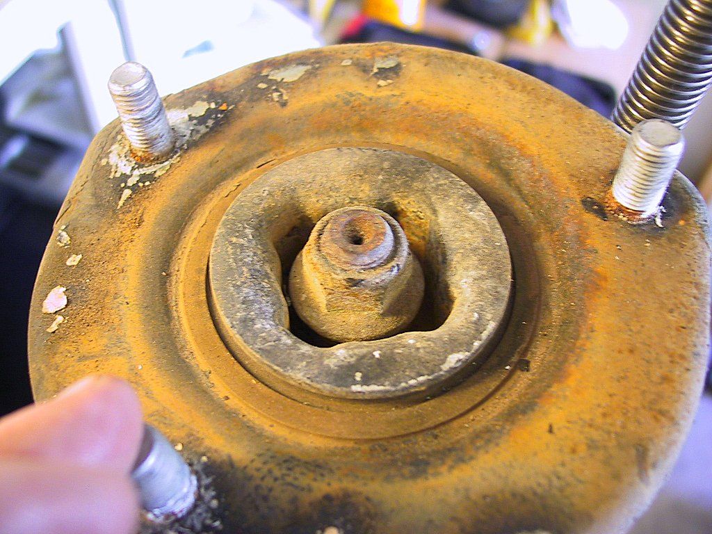
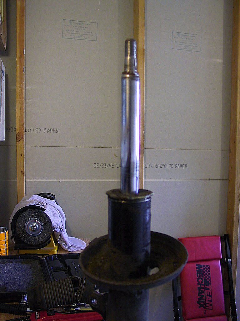
OK, here's a tip that I learned the hard way: take a 19mm deep socket and loosen the nut on the top of the strut rod. Just loosen it enough to make removal easier later on.
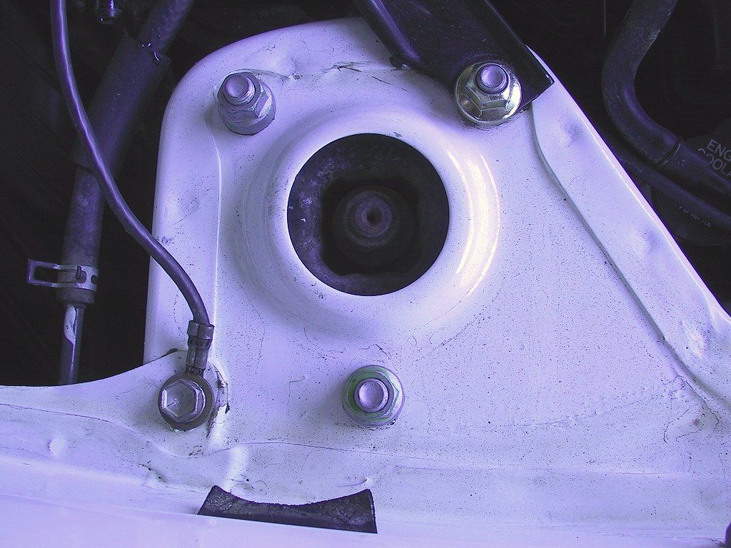
Now remove the three 14mm nuts that secure the top of the strut tower to the body.
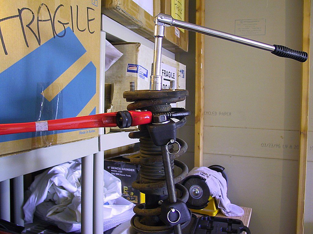
If you were unable to remove the upper link stud before, try to remove it as you slowly compress the strut. I strongly encourage you to never put your hand where it could be injured by a sudden slip of the brace.
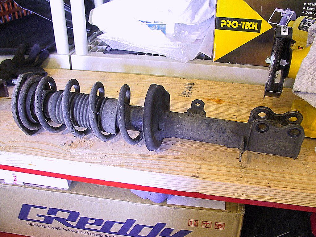
As you can see, there's only a small rip in the strut boot. This was, by far, the best boot of the bunch. One of them was in shreds.
The pipe wrench is gripping the round "collar" directly below the upper suspension mount. If that fails, you'll need to lay the strut on its side and secure the upper suspension mount in the vise. Then you should be able to loosen the strut rod nut. I had to do this with one of the rear struts, but I don't have a photo.
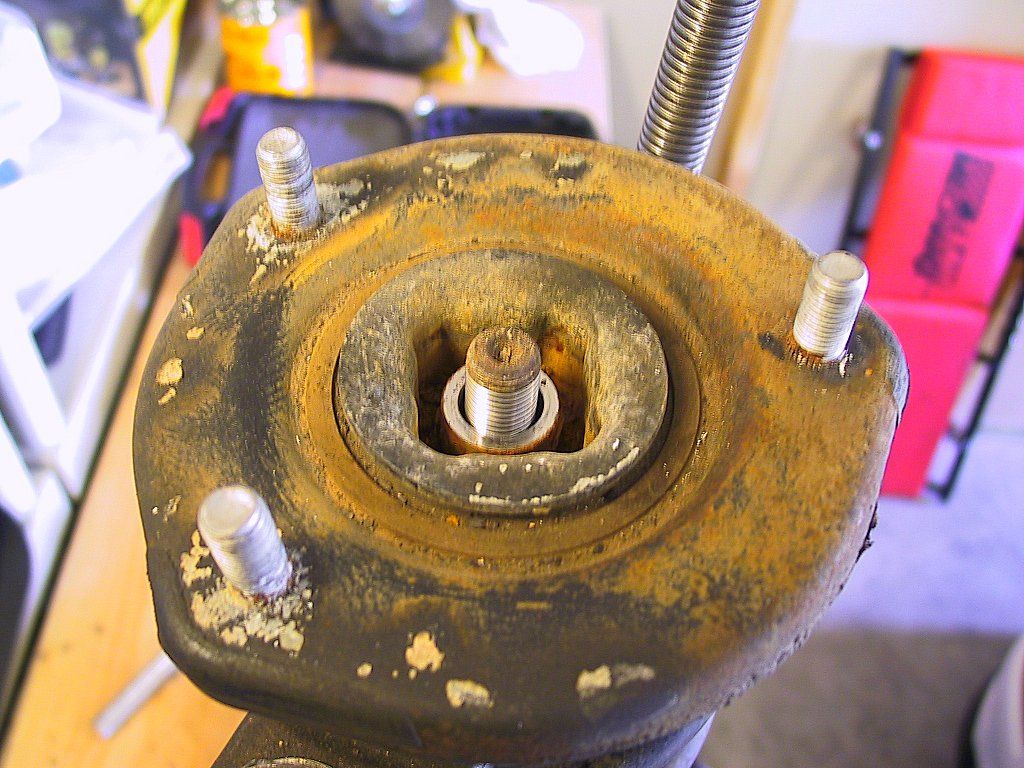
Slip the spacer out and put it aside. The Tokicos include a new nut, but not the spacer.
If the upper mount does not pop off, then you'll need to use brute force, persuasion, harsh language, whatever it takes. Trust me, it's simply there by the force of friction. If you wish to know what lengths it takes to remove it, skip ahead to the description of the front strut disassembly I experienced.
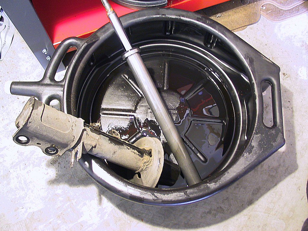
The next challenge is the large (2") nut that retains the internal strut mechanism. It's often referred to as the gland nut, but I'm not sure where that terminology originates, not whether it's correct.
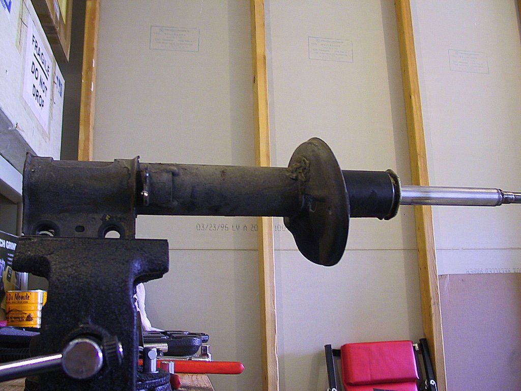
Get a large pipe wrench on the nut and slowly crank it off. Be careful not to gouge the strut body too badly. I had to fit a long steel tube as a handle extender on my pipe wrench to apply enough leverage.
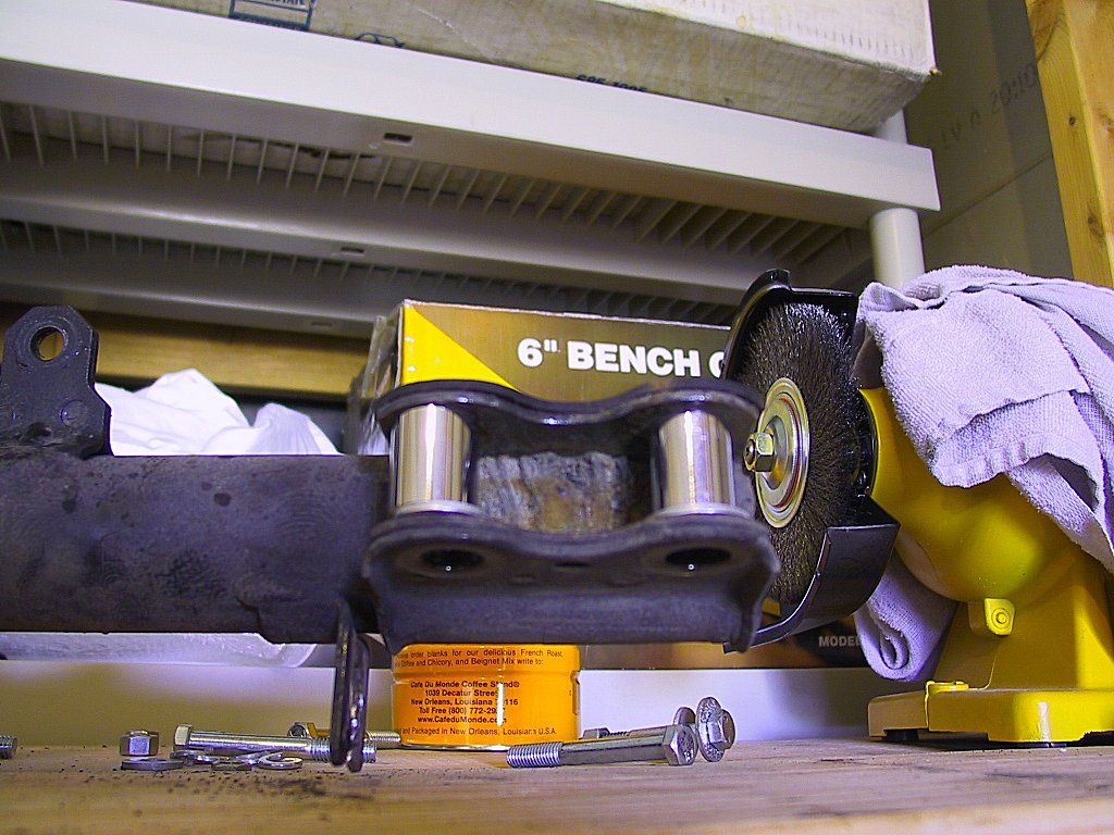
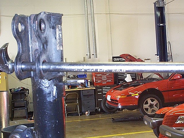
Aron Seiler offered a tip for removing the gland nut that I never thought of. He mounted the strut upside down in a vise, with the jaws securely holding the gland nut. He then slipped a long drift through the mounting holes on the strut body, and twisted it loose. Here are a couple of photos Aron provided:
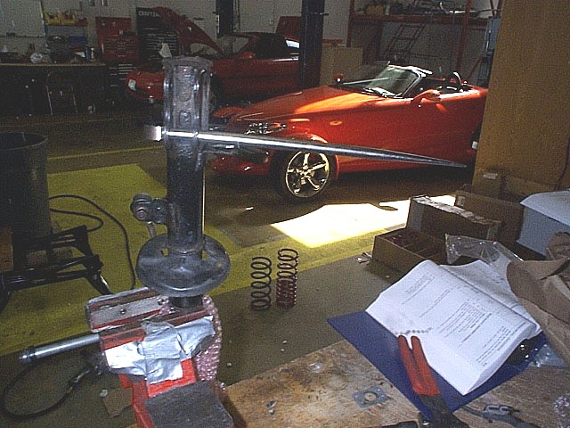
Ready for reassembly! Well, maybe after some serious cleaning. We'll skip that part, since it's simply mindless, boring, "fill-your-lungs-with-terrible-solvent-odors" labor. I also took this time to wire-wheel all the nuts and bolts. I even cleaned off the rust that had accumulated on my brake rotor. I live in Las Vegas, so rust is not a big problem (with average humidity less than 10%), but the car came from the Midwest, so there's some history there.
In my case, this was an excellent time to take a much needed break. Thai food, anyone?
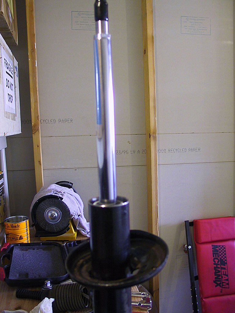
You'll need to add some lightweight oil between the strut cartridge and the strut housing to improve heat transfer. It doesn't take much, and Tokico recommends filling to within 1-1/2" to 2" of the top of the housing tube. I used some 15W motorcycle fork oil I had laying around, since it was available. Fork oil is a bit pricey for this duty, but I knew I'd never use it, since 15W results in really stiff fork action in a motorcycle.
Tokico provides a new gland nut (I guess they know how badly a pipe wrench can chew up the old one). They also recommend both a torque setting (~90 ft. lbs.) and a minimum "spacing" that describes the amount of threads showing. If this spacing is below the minimum, Tokico includes a spacer washer that should be inserted atop the cartridge before the gland nut is installed. It was not necessary in my case.
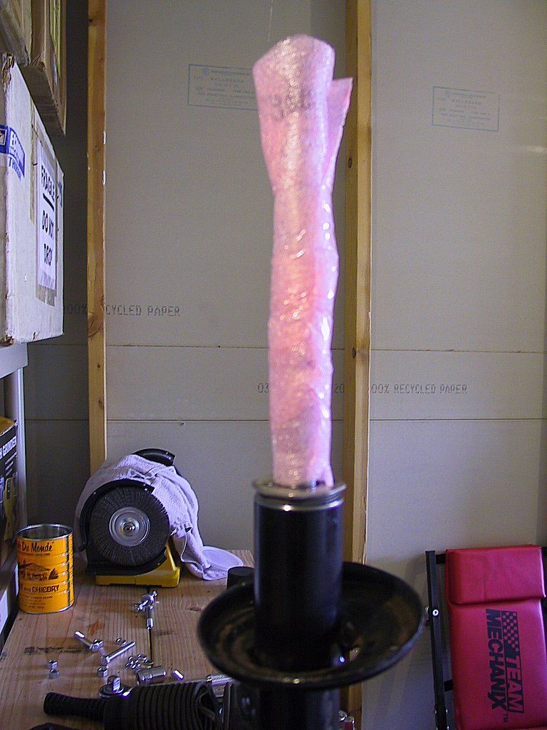
UPDATE (02-20-01): KYB ships wire ties with the boot to retain it to the strut body. I found that these ties are too weak to hold the boot at full extension, so I replaced them with a heavier tie. If that still comes loose, I think I'll use stainless steel screw clamps instead.
This was really hard, and another break was called for (to ease my back muscles).
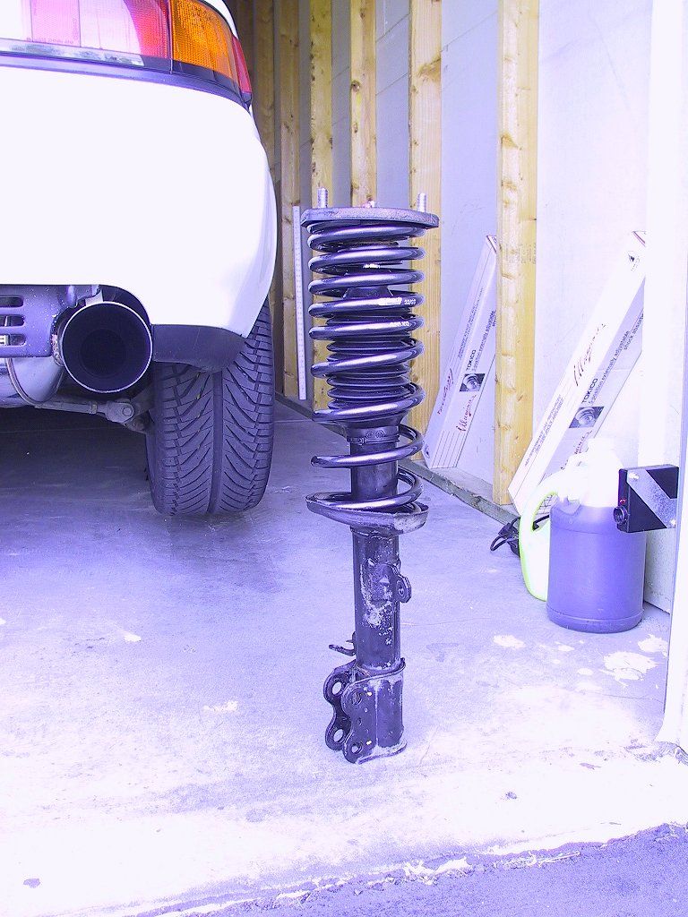
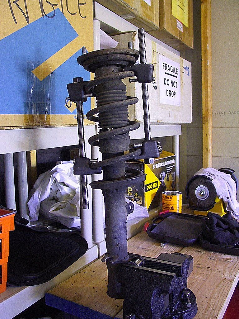
Ready to go!
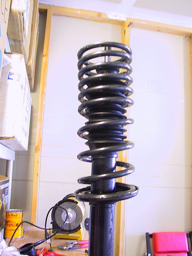
There's really not enough room to fit spring compressors, so I ended up using the same "mickey-mouse" tools I used to remove it. Next time, I'll find a better brace to use for compressing the strut in place.
Page ![]() 1 2
1 2
![]()