|
Page  1
2
3
4
1
2
3
4
 |
|
|
GReddy Intercooler Installation
(continued)
|
|
|
At this stage, if your only goal was to replace the IC and fan, you can
begin reinstalling the intake pipe and intercooler hoses. My project ran a
slightly different course, but I will describe the last few steps of the
IC installation.
|
|
|
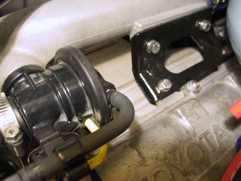
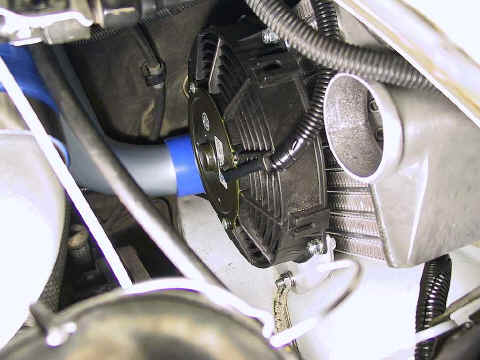
Replace the stock intake pipe bracket and pipe. I used stainless steel
bolts in place of the stock bolts, and I'd painted the rusted bracket in
the meantime.

|
|
|
My overall satisfaction with the GReddy kit was tempered by the hose/pipe
components. My first complaint is that the pipes are a bit too long, which
means the connecting hoses have almost no internal clearance between the
two ends of each pipe being joined.
The connecting hoses seemed to be a bit undersized in diameter, which
made me feel as if I was stretching the hose over a too-large pipe. In
addition, the lengths of hose are very short, which means the clamps have
very little hose to work with, especially when using the wider T-Bolt
clamps. A wider clamp is generally desirable, but not in this case.
To make matters worse, the instructions are very unclear about which
hoses go to which pipes. The diagrams are difficult to read, and the text
is vague. They probably should have simply left the instructions off
entirely with a simple message, "Figure it out on your own",
since that's what it comes down to.
OK, enough ranting.
|
|
|
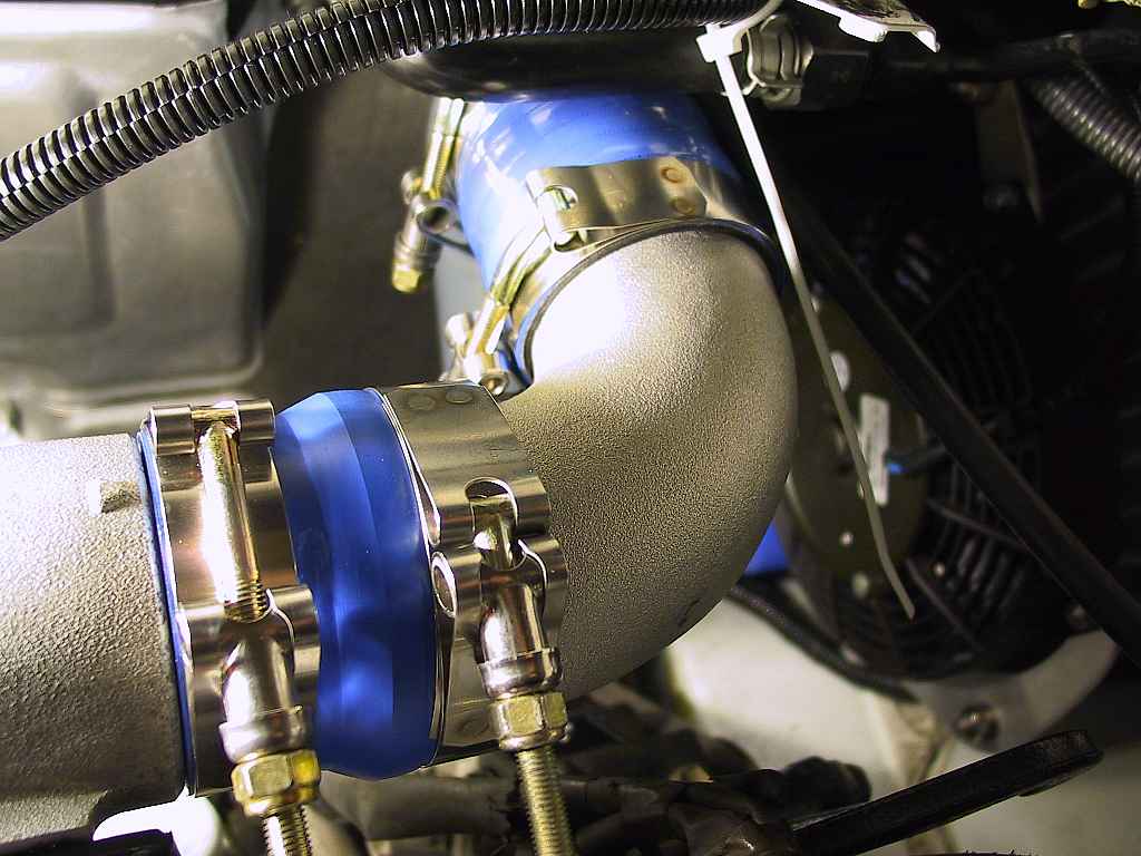
The larger of the two aluminum elbow pipes (90ş) attaches to the stock
intake pipe with one of the two "adapter" hoses, e.g., a hose
with different diameters on each end:
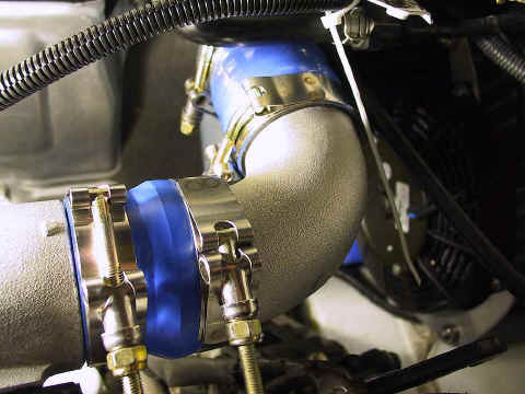
The long "S" pipe attaches to the other end of the 90ş
elbow with one of the six short lengths of silicone hose.
|
|
|
I incorrectly attached the other end of the "S" pipe to the
lower intercooler pipe with the other adapter hose. It seemed to fit
correctly that way:
I should have guessed that if it seems to fit correctly, I must have done
something wrong!
|
|
|
|
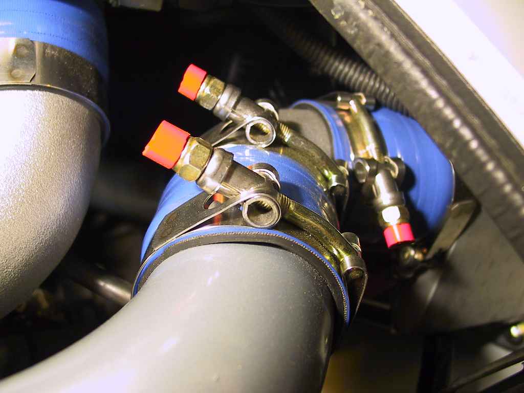
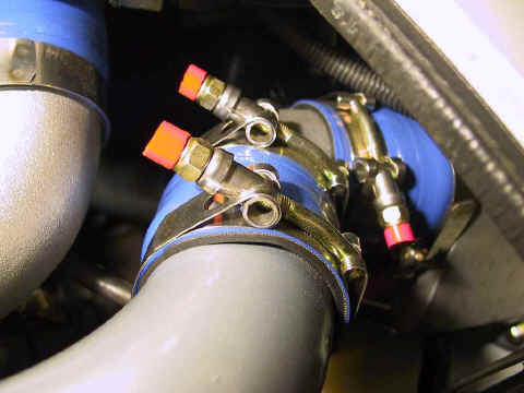
Once the lower hose was secured (I
thought!), I used two more hose sections to attach the smaller elbow to
the upper IC outlet and the upper pipe (the one with the two fuel-injector
bungs) to the elbow:
|
|
|
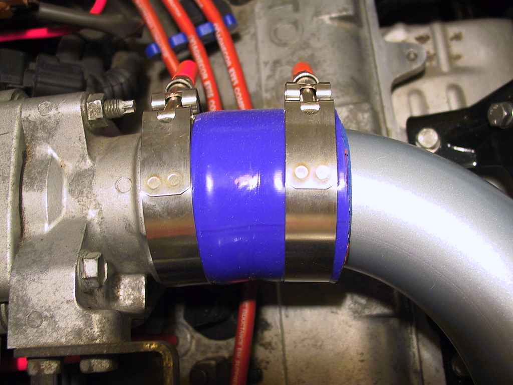
The other end of the upper pipe connect to
the throttle body inlet. Here's where I realized I'd attached the wrong
piece of adapter hose on the lower IC inlet.
Instead of removing the lower inlet
hose, I instead cut off about 1˝" of one of the hose sections in the
GReddy kit. I then fit a section of silicone turbo hose I had laying
around over top of that hose and secured it:

This solved two problems: it eliminated the need to remove the lower hose
on the IC inlet, and it enabled me to install a long enough section of
hose to securely tighten the T-Bolt clamp. However, I don't recommend this
as a "solution".
|
|
|
GReddy includes some heat heat-resistant
cloth, but their instructions on which pipe it should be wrapped around
are confusing. I chose to leave it off entirely, since the stock pipes did
not see fit to use it.
|
|
|
Reinstall the strut braces. This is one area where the BGB lists incorrect
torque settings in at least one are of the book. I "think" a
reasonable setting is 45 ft. lbs., but in one location the BGB asks you to
crank this little 14mm nut to 59 ft. lbs. The front strut bolts call for
36 ft. lbs., so I think anything around 40 ft. lbs. is more than adequate.
|
|
|
If you have used the stock fan
temperature sensor and power circuit, your installation is finished, save
for testing the installation. In my case, that lower hose I had installed
in error was not tightened down properly, and blew off as I was
accelerating down a freeway ramp, leaving me along the roadside tightening
a difficult-to-reach clamp on a hot engine. But it wasn't too bad, and I
got it working. I immediately re-tightened all of the turbo hoses.
|
|
|
|
|
|
Page
1
2
3
4
|
|
|
|
|
|
Dave Martin
1993 MR2 Turbo |
|