This page was developed by Alex Koralewski, whose web site is located
here.
Toyota T-VIS System
Variable Air
Induction Systems
Purpose of
Variable Induction Systems
Toyota engines
have taken advantage of four valves per
cylinder technology throughout the later half of the
1980s. This cylinder head and valve arrangement allows
better engine performance at high rpm by improving
the engine's volumetric efficiency.
Enlarging the
port area of the intake valves does little
for engine breathing unless the intake manifold is
enlarged as well By enlarging the intake manifold runners
and plenum area, a greater volume of air is available
to the intake valves at high engine rpm.
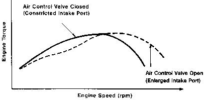
At lower engine
rpm, however, an enlarged intake runner
has a negative effect on volumetric efficiency due
to reduced air velocity at the intake valve. This characteristic
causes a four valve engine to have a very
healthy torque curve at high engine speeds but a
comparatively weak one at lower engine speeds.
The variable
induction system is designed to give a four
valve engine the best torque characteristics at both
low and high engine speeds. This is accomplished
by changing either the effective length
or diameter of the intake runner through the use
of an intake air control valve. This valve is activated
by an ECU controlled Vacuum Switching Valve
(VSV) and vacuum actuator.
Toyota
Variable Induction System (T-VIS)
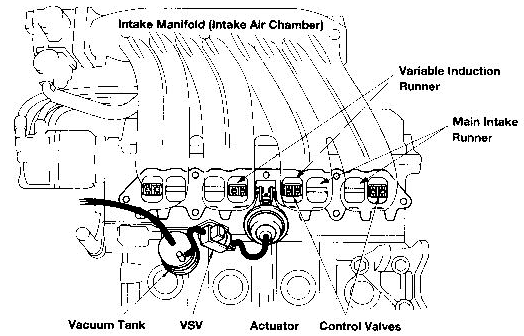
T-VIS System Components
The T-VIS system
is the fast variable induction system
used on Toyota engines built for use in the U.S.A.
The system is used on the 3S-GE, 3S GTE, and 4A-GE engines. The induction system
consists of the
following components:
- Four
individual intake air control valves supported
on a common shaft
- Vacuum
actuator which rotates the shaft
- ECU
controlled Vacuum Switching Valve
(VSV)
- Vacuum
storage tank
T-VIS
System Operation
The
intake manifold feed for each cylinder is divided
into two separate runners. The main runner
is provided for low speed operation while
the other is provided as the variable induction runner. Each intake runner is
purposefully designed to flow approximately half of
the air volume required by the engine at full
power. The variable induction runner is equipped
with an intake air control valve.
The
main intake runner supplies air to the intake
valves at low speeds. Intake air flows at
high velocity due to the long and narrow runner
design. The intake air control valve opens
the variable induction runner when adequate engine rpm is reached, thereby
providing sufficient
air volume for high speed operation. This
design makes it possible to maintain strong engine
torque at both low and high engine rpm.
The intake air control valves, installed between the
cylinder head and intake manifold, are all closed
simultaneously by the vacuum actuator when
vacuum is applied. When vacuum is relieved
from the vacuum actuator, the air control
valves return to their fully open position.
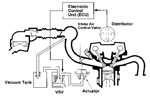
When
the engine is running below the 4000 to 5500
rpm threshold, manifold vacuum from the vacuum
storage tank is supplied to the actuator
through the ECU controlled VSV. The vacuum
storage tank is required as a vacuum reservoir
to hold the intake as control valves open
whenever the engine rpm is below the operating
threshold but manifold vacuum is too low
to hold the intake air control valves closed.
When the pre-programmed rpm is reached, the
ECU signals the VSV to switch vacuum away
from the actuator and open an atmospheric bleed. This action causes the actuator
to
release the air control valves to their open position,
allowing maximum air volume to enter
the cylinders.
T-VIS
Vacuum Switching Valves (VSV) and Operating Strategies
There
are two different VSVs
used for T-VIS control depending on application.
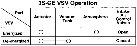
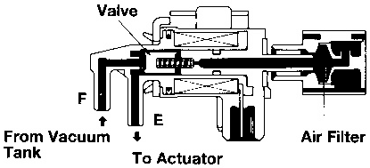
The 3S-GE engine uses a VSV with a normally
open valve. This VSV passes vacuum to the
actuator when de-energized by the ECU. During low
speed operation, the ECU keeps the VSV de-energized
to keep the actuator applied, closing the air
control valves. At high speed operation, the VSV is
energized, blocking the vacuum supply to the actuator
and bleeding any trapped vacuum. This allows
the air control valves to open.
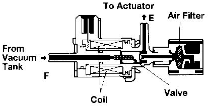
The
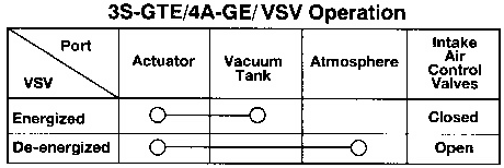
3S-GTE, 4A-GZE, and 4A-GE engines use a VSV
with a normally-closed valve. This VSV passes vacuum
to the actuator when energized. When the engine
is operating at low speed, the VSV is energized,
allowing vacuum to apply the actuator and
hold the air control valves closed. When the ECU
parameters are met to open the air control valves,
the ECU de-energizes the VSV to block the vacuum
signal to the actuator and bleed trapped vacuum
from the actuator diaphragm.
3S-GTE
Fuel Judgment Strategy Using signals from
the knock sensor, the 3S-GTE engine incorporates
a fuel judgment strategy to control maximum
turbo charger boost pressure and T-VIS operation.
When fuel is judged to be of premium grade,
the T-VIS system functions as outlined above. The
ECU will de-energize the VSV when engine speed
reaches approximately 4200 rpm. When
fuel is judged to be of regular grade, however,
the ECU operates the air control valves based
on throttle position. When the IDL contact is
closed (closed throttle), the VSV will be energized,
allowing vacuum to pass to the actuator, closing
the air control valves. When the IDL contact
opens, the ECU de-energizes the VSV, blocking
the vacuum supply to the actuator, causing
the air control valves to open.
Acoustic
Control Induction System
The Acoustic Control
Induction System (ACIS) is
used on the 7M-GE, 3VZ-FE and 2JZ-GE engines. As with the T-VIS system, the
purpose of this system is to improve engine torque throughout
the engine rpm range. The system consists
of the same basic components as T-VIS and
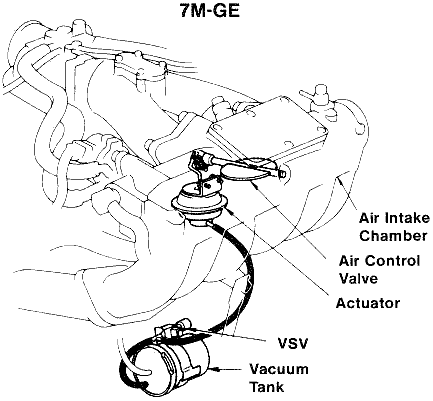
operates similarly. The ACIS system uses a
single intake air control valve located in the intake
as chamber which effectively changes intake
runner length as it opens and closes.
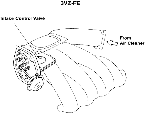
ACIS Air Control Valve
The main
difference between T-VIS and ACIS is
the single butterfly air control valve used in the
ACIS system. This valve is located in the center
of the intake manifold plenum and is designed
to divide the plenum into two sections, a front chamber and a rear chamber. By
dividing the
manifold plenum into two chambers, the effective manifold money length can
be controlled by
opening and closing the valve.
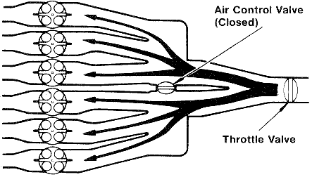
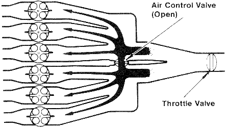
ACIS
System Operation
The
ECU controls the position of the intake air control
valve based on input signals from throttle angle
(Vta) and engine rpm (Net. The VSV which
controls the vacuum supply to the actuator, is
normally closed and passes vacuum to the actuator
when it is energized by the ECU.
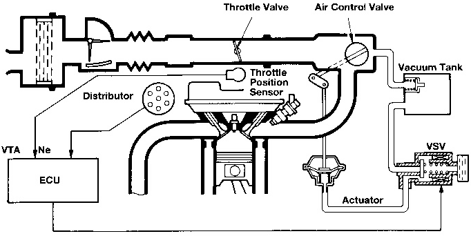
By energizing
the VSV vacuum is passed to the actuator,
closing the air control valve. This effectively
lengthens the intake manifold run- the velocity
of intake air flow at the intake valve. By
de-energizing the VSV, vacuum to the actuator is blocked
and trapped vacuum is bled off of the actuator
diaphragm. Without vacuum, the air control
valve opens, effectively shortening intake runner
length. This logic is the same as that used on the
3S-GTE T-VIS system.
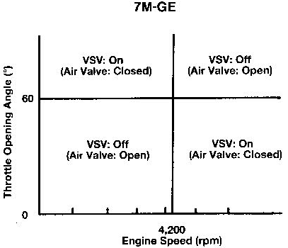
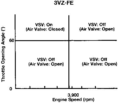
The following charts represent ECU operating strategy
for the ACIS system.
The T-VIS and ACIS systems are wired to the ECU
as shown in the electrical wiring diagram. During
troubleshooting, a voltmeter can be used to monitor
the ECU command to the VSV.
Voltage measured at the T-VIS or IACV terminal
of the ECU will be high (battery voltage) until
the ECU energizes the VSV. The ECU logic to
drive the air control valve VSV, and the voltage measured,
will differ depending on the applications and
strategies outlined above.
|


