|
Page  1
2
1
2
 |
|
|
Installing a J&S Safeguard Ultra II
(continued)
|
|
|
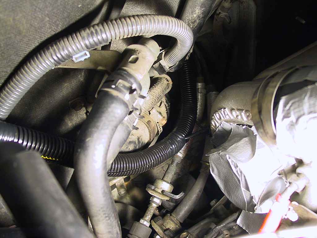
I gathered up all of the wires coming out of the
tunnel and sorted which bundles headed in which direction. I then wrapped two
different bundles (one in each direction) and routed them further into the
engine compartment. In addition, there were some additional wiring bundles for
the AVC-R pressure sensor and solenoid valve, which were located on opposite
sides of the engine compartment. Where possible, I wrapped these up in the
sleeving to present a clean, organized appearance.
Here are a couple photos:

I then forced the sleeving as far up the wire bundles as I could and taped them
off with electrical tape.
|
|
|
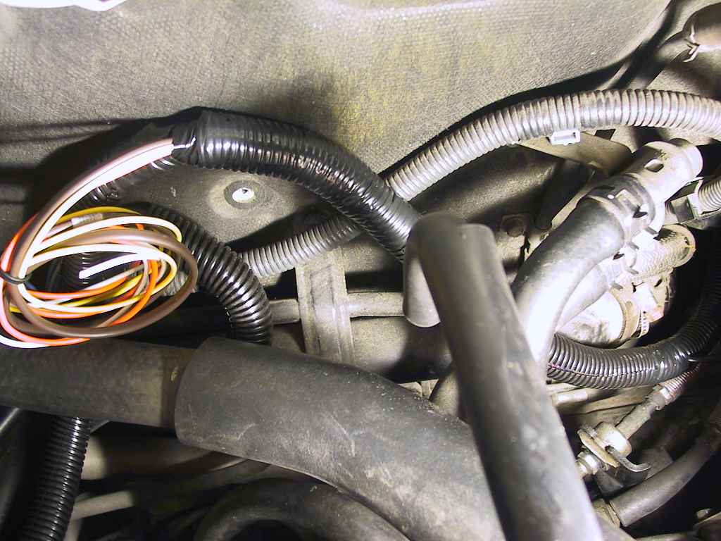
On the left-side bundle, when I reached
the fuse panel I cut an opening in the sleeving and fed out the EGT
gauge wires as well as the IC fan switch wires:

|
|
|
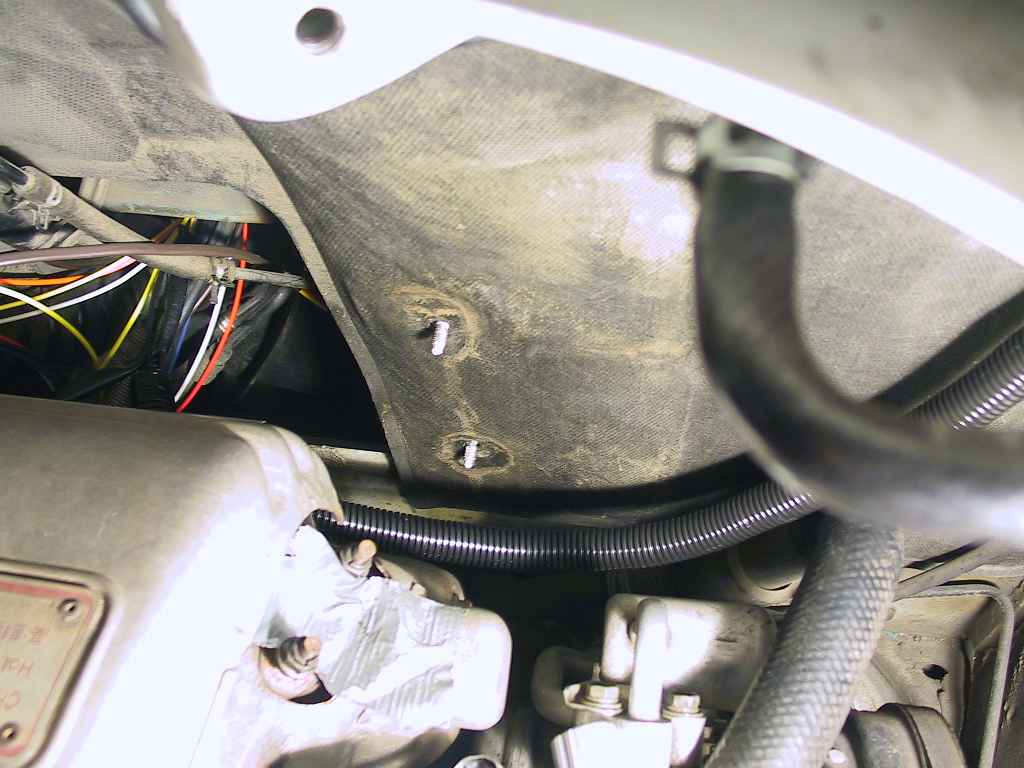
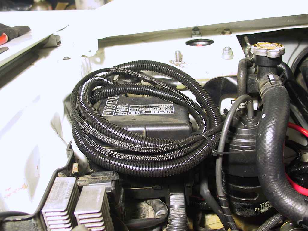
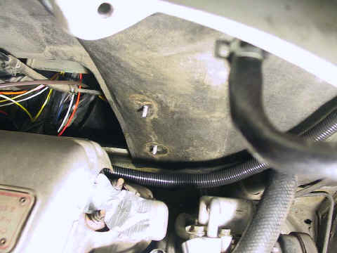
I continued routing the remaining bundle towards
the trunk, cutting another opening in the sleeving that would lead to the AVC-R
solenoid valve mounted on the left wheel housing. I then coiled up the bundle to
search for a suitable access point into the trunk:
|
|
|
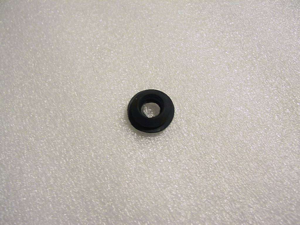
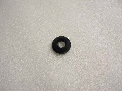
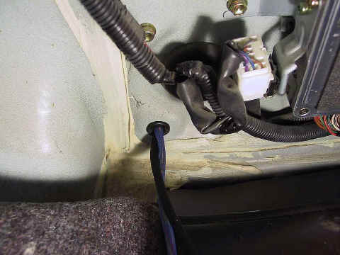
I opened the trunk and pulled back the trim
material to expose the ECU and associated electronics. In the lower left corner
was a rubber plug that fit in a ľ" hole. I removed the plug and cut out
the center:
|
|
|
I removed the fuse box from its mounts,
and managed to work the two remaining cable bundles into the hole from
the engine compartment. I then trimmed back the ribbed sleeving to the
proper length:

I re-mounted the fuse panel and turned my attention to the trunk.
|
|
|
At this point, stop what you are doing and disconnect
the negative lead of your battery. If you have enabled the security
features of your stereo, be advised that you will need access to the
security codes to re-enable it when power is restored.
|
|
|
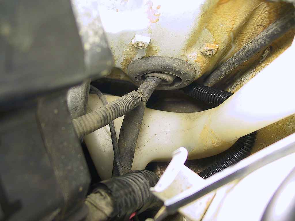
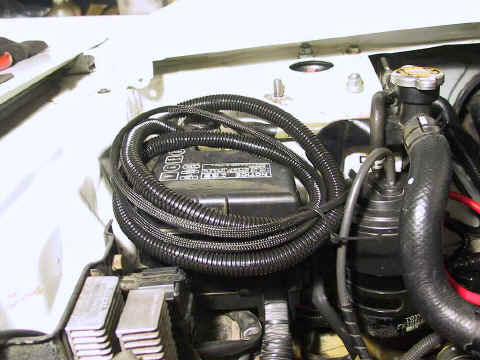
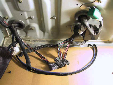
Here's a look at the trunk-mounted
electronics. You can spot the two cable bundles (in different colored
braided sleeving) entering from the lower left:
|
|
|
I slipped the plug-turned-grommet over the
cable bundles and pushed it into place, where it fit perfectly:
|
|
|
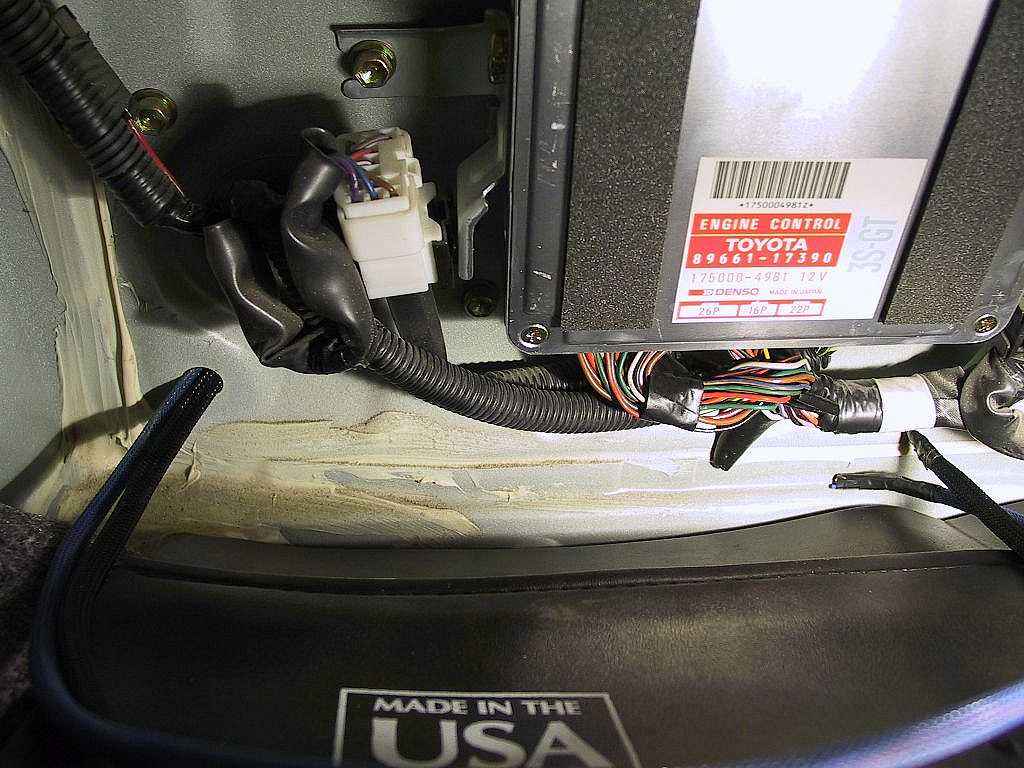
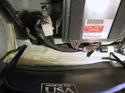
I removed the ECU unit to be able to tap into the
wiring harnesses more easily:
|
|
|
Here's where things get interesting. While
it should be a fairly straightforward matter to splice the wires from the
Safeguard and AVC-R harnesses into the ECU harnesses, the manufacturers
make it difficult. Both APEXi and J&S give barely adequate
instructions. Toyota, for their part, saw fit to change the wire
assignments from one year to the next. Without a BGB for the current model
year of your car, you're going to be doing some head scratching.
For one thing, it's not made clear in
the instructions whether references to connector pins refer to the harness
pin or the ECU pin. This means that you are kept guessing as to exact
location.
If you have the Ultra II, you'll run 7 wires back to the ECU.
|
|
|
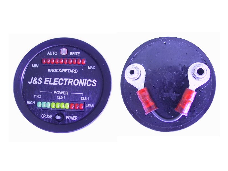
I received the J&S Dual Monitor gauge about a
month after the Safeguard arrived. Here's a photo of the gauge:
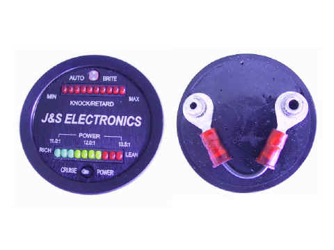
The gauge has a knock monitor across the top and a dual-mode (Cruise/Power)
AFR display across the bottom.
|
|
|
I had already installed the Safeguard, and now I was faced with fishing two
more wires for the AFR module. I decided that pulling a complete bundle of
9 wires in a braided sleeve would be easier than fishing two more small
(22 AWG) individual wires.
The following instructions worked on my
car, a '93 U.S.-spec Turbo. The warnings about "you are on your
own" are doubly important in this, since you can fry your ECU in the
worst case scenario.
|
|
|
The Ultra II has two connectors. The main connector has 8 terminals, 5 of
which are used. The smaller 2-terminal connector disables the fuel
cut.
The ECU has 3 connectors. According to the BGB, "A" is the
22-pin connector, "B" is the 26-pin connector, and "C"
is the 16-pin connector. The pin numbers below match the BGB designations.
I ran the following wire colors from the Safeguard control unit to the
ECU harness (from left to right). Connections to wires A12, B26, C6, and
C13 are taps onto the existing wire. Connections to B20 and C5 require
cutting the wire in half and inserting the J&S components into the
circuit loop. The J&S instructions show this clearly in their
diagram.
Thanks to Steve Cornell for
pointing out that this wiring
configuration for the Ultra Version 2 is not the same as the Ultra
Version 0. Steve also pointed out some errors I'd made in transcribing the
main connector's terminal assignments to this page.
The Ultra
Version 0 does not include the Boost Retard and Fuel Cut features, and there is
no auxiliary connector, only the main connector.
|
|
|
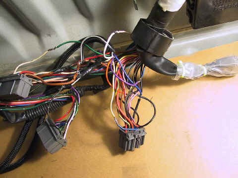
Here's a shot of the various splices. These include the
AVC-R splices as well. I'm not sure if it's helpful, but ignore it if
it's of no use to you.
|
|
|
One problem I ran into during the installation of the
gauge was with the cables J&S ships with the unit. The interface for
the knock display is a 10-foot audio cable with straight plugs on both
ends. The straight plug was too large to allow me to close the lid on
the console where the control unit was located, and adding a right-angle
adapter made the connection too long.
I searched the web unsuccessfully for a right-angle patch cable, so I
ended up cutting the right-angle adapter apart and soldering the wires
directly to its internal lugs. I then re-fitted the vinyl casing, added
a little hot glue and some electrical tape, and it fit perfectly.
|
|
|
Once the components were all installed, I set about
trying things out. I quickly learned that the initial calibration
guidelines included with the J&S instructions did not work for me.
Here is my advice for setting up the Safeguard:
- Follow the J&S instructions for setting the dip switches and
the fuel cut voltage
- Turn all adjustable pots to the extreme counter-clockwise
position. This is the "OFF" position.
- I found (and this was confirmed by other users) that the knock
detection is far too sensitive for my taste. The best setting was
obtained by turning the sensitivity control (far left on the control
unit) very slightly clockwise and then driving around without
initiating much boost. If you turn it too far, it will begin
retarding the ignition simply due to normal mechanical noise.
- I have my boost/retard turned off. Perhaps it will prove valuable
in the future.
|
|
|
If you do not have the dual monitor gauge, setting the
knock sensor is difficult. First, the control unit is difficult to
locate where you can see the single LED that indicates knock. Second,
the single LED is difficult to read while driving.
The dual monitor enables you to fine-tune the sensitivity. This is
vital if you don't wish to lose power under boost.
|
|
|
As I use this tool more, I will update this page with
any additional tips or techniques. I'm planning on replacing the Toyota
knock sensor with a GM unit I obtained from ATS Racing, and that will
require re-calibration of the knock control system.
|
|
|
|
|
|
Page
1 2
|
|
|
|
|
|
Dave Martin
1993 MR2 Turbo |
|